Skip to comments.
Bridge Collapse Caused By Design Flaw, Not Maintenance
Captain's Quarters ^
| Jan. 15, 2008
| Ed Morrissey
Posted on 01/15/2008 10:21:06 AM PST by jdm
The collapse of the St. Anthony Bridge in Minneapolis started with a design flaw in the gusset plates, confirming suspicions that arose in the first week of the investigation. A source familiar with the conclusion told CNN earlier this morning that the NTSB will announce that finding later today, ending speculation that poor maintenance caused the deaths of 13 people last August:
Federal investigators have identified a design flaw as the cause of last year's Interstate 35W Minneapolis bridge collapse that killed 13 people, a congressional official said Tuesday.
The official, who was briefed by the National Transportation Safety Board, said that investigators found a design flaw in the bridge's gusset plates, which are the steel plates that tie steel beams together.
The official spoke on the condition of anonymity so as not to pre-empt an update being provided later Tuesday by the NTSB chairman, Mark V. Rosenker.
The findings are consistent with what the NTSB said about a week after the August 1 collapse, in which the bridge plunged into the Mississippi River.
Within hours of the collapse, some critics here and nationwide pointed to the collapse as the end result of underfunded infrastructure. One local crank blamed the head of the Taxpayers League of Minnesota for turning bridges into deathtraps six hours after the bridge failed. Others demanded a gas-tax increase to bolster the $2.2 billion annual budget for MnDOT, the agency which spends three times more than the budget for public safety every year.
Instead, we find out that the bridge design doomed it from the start. The bridge was built in a post-war period where streamlining and efficiency created a lot of questionable bridge designs; a few years later, architects returned to the more robust pre-war concepts. This collapse showed why that was necessary, and it serves as a warning to those who skimp on redundancy as unnecessarily costly in building infrastructure.
Minnesota has already begun building the replacement bridge, which we hope will be complete by the end of the year. Everyone can learn lessons about this bridge collapse, especially those who attempted to exploit it for their own political agendas.
UPDATE: USA Today has more:
In the wreckage of the I-35W bridge, investigators found 16 gusset plates that were fractured, said one of the officials. Eight of the plates were in the location on the south side of the bridge where the collapse began, according to that official.
The fractures prompted engineers to calculate whether the plates were adequate to hold the bridge together. What they found was that the half-inch thick plates should have been an inch thick — double the size.
And without a redundant support structure, once the first gusset plate fractured, the rest would have failed as the weight of the bridge shifted and generated momentum.
TOPICS: Business/Economy; News/Current Events; US: Minnesota
KEYWORDS: 35w; bridge; bridgecollapse; collapse; designflaw
Navigation: use the links below to view more comments.
first previous 1-20, 21-40, 41-60, 61-80 ... 101-117 next last
To: Abigail Adams
I just don’t believe this conclusion. It is too convenient. It lets everyone alive off the hook. I have gone through a number of AISC code revisions. EVERY one of them increased the thicknesses (and/or lowered the allowable stress) when compared to the previous one at least somewhere in the code. Over 40 years, they add up to quite a difference.
So if they were comparing the as-built sizes with the current code, they are guaranteed to find a “flaw” in the design. In addition, the number of lanes was increased at sometime between the original building and the collapse. That was bound to increase loads. Who approved that decision? Again, checking calculations with the current number of lanes is guaranteed to find a flaw.
In addition, the inspection report showed that there were NUMEROUS cracks in those very gusset plates and many of them were only half the original thickness because of serious corrosion. That was all noted in the reports — and ignored. If they intend to ignore reports, why bother even having them.
This is a whitewash. A coverup.
To: festus
In the report it states that the gusset plates should be stronger than the connected beams. Therefore, when bridges are reanalyzed it is standard practice to assume they are and not reanalyze the gussets.
Also, not unusual for an structural design problem to remain hidden for years before failure. The plant I work at had an original design error that let lose after being in service 35 years.
42
posted on
01/15/2008 6:49:25 PM PST
by
Dewey1960
(Not a structural engineer - but I know some.)
To: jim_trent
From the article above:
The bridge, built in 1967, was designed by Sverdrup & Parcel, a prominent firm that also designed Busch Stadium in St. Louis, the Superdome in New Orleans and the Chesapeake Bay Bridge-Tunnel.
The founder of the firm, Leif Sverdrup, is dead. The company is part of Jacobs Engineering Group in Pasadena, Calif., which did not return calls.
And from wikipedia:
Sverdrup & Parcel was an American civil engineering company formed in 1928 by Leif J. Sverdrup and his college engineering professor John I. Parcel. The company worked primarily in a specialty field of bridges. Many of the company’s projects were located in the St. Louis, Missouri area near the company’s headquarters.
So one of the founders is dead, but that doesn’t mean that the particular engineer who designed the bridge is not still with us.
To: Dewey1960
To: Abigail Adams; Spktyr; Ramtek57; fatima; Attention Surplus Disorder; 1COUNTER-MORTER-68; Ramius; ...
Not long after my last post on this subject, I located the failure point, the U10 East Truss gusset, in the post collapse imagery, ran analysis on both post collapse and precollapse imagery of that gusset, and satisfied myself as to the cause and nature of the collapse.
I did not post this additional analysis at that time, for three reasons:
1. The results did not change my original conclusion, that the U10 East Truss gusset fractured as a very early, and probably the prime trigger for the full collapse.
2. The additional analysis was technical in nature, probably not of interest to non-engineers.
3. Other things were going on at the time, demanding my attention.
This post is a shortened version of what I would have posted then, if time had allowed and there had been strong reason to do so.
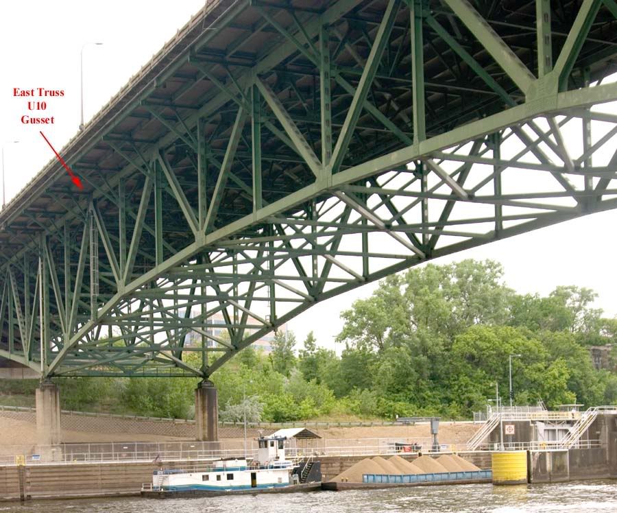
Here is a pre-collapse image of the I-35 bridge, looking southwest, with the U-10 East Truss gusset plainly marked:
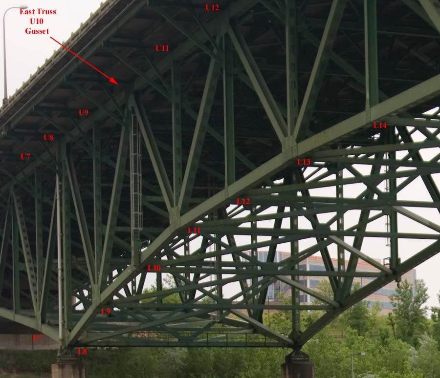
Here is a tighter zoom of the above image, showing discoloration on the U10 East Truss gusset, with other critical points labeled for reference:
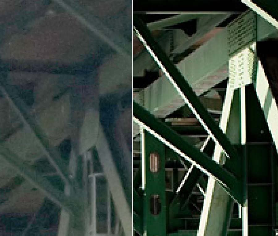
Here is an extreme zoom of the above images, isolating the U10 East Truss gusset, in comparison with a similar gusset which is in better condition and showing more detail:
Given before and after imagery, I decided to reconstruct the U10 East Truss gusset, as seen in the post collapse imagery, for analysis purposes. The following image gives an idea of the method I used to determine scale:
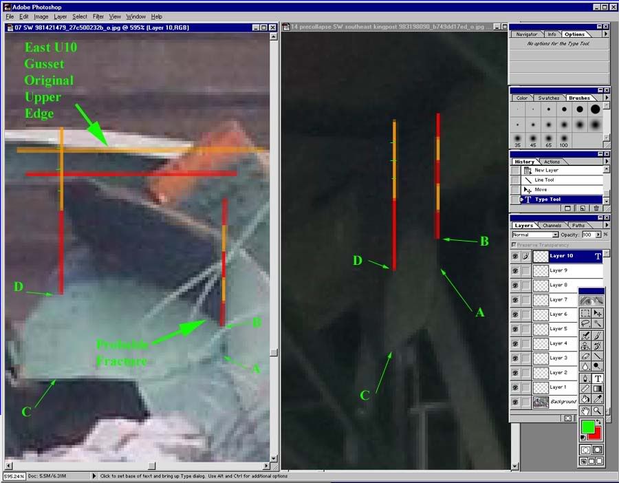
By taking two distances visible in both pre- and post collapse imagery, distances AB and CD in both panes, and comparing them to distances only visible in pre-collapse imagery, I was able to approximate the U10 East Truss gusset for size, orientation and scale, and flatten it back out, in the post collapse imagery, so we have a better idea exactly where the fracture took place, and can speculate as to cause:
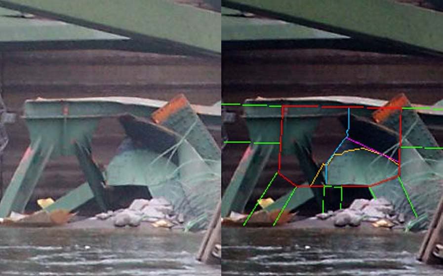
In the above image, right pane, the U10 gusset is outlined in red, the original structural members connected by U10 are marked in green, the pre-collapse discoloration of the U10 gusset is marked in yellow, the post collapse fracture line is marked in blue, and the post collapse fracture/folding of U10 is marked in violet.
The image below shows a wider view, including the reconstructed U10 gusset, with several interesting points labelled:
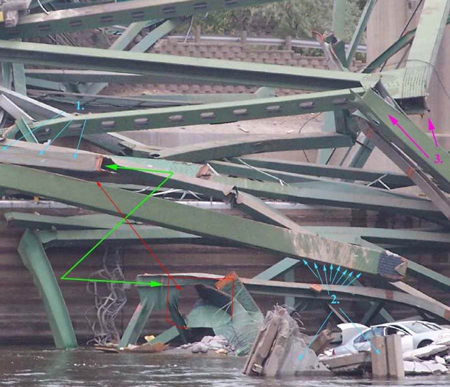
At left center, the U9-U10 topchord shows a longitudinal scar, marked with the arrows emanating from the numeral 1. In my opinion, this probably indicates that the U9-U10 topchord slid out from under a considerable gravity load during early failure. In other words, the road deck did not fail precisely at the U10 gusset, it broke further south, and a big piece of road deck scarred the U9-U10 top chord on the way down.
The green arrow shows how the two pieces fit together before the collapse, and the red arrow shows a piece of the U10 gusset still attached to the U9-U10 topchord. Under extreme magnification, the U10 gusset fragment still attached to the U9-U10 topchord shows the same discoloration noted previously.
Additionally, the above image reveals another interesting observation. Scrapes and discoloration on the collapsed L9-U10 diagonal clearly match the deck concrete, as indicated by the arrows emanating from the numeral 2. The L9-U10 diagonal came to rest upside down after the collpase, and the radial nature of these scrapes is clearly apparant.
Either an explosive fracture of the bridge deck took place in close proximity to this member, or else this member was subject to a prolonged shower of fractured concrete debris as it fell, and the scuff marks, and therefore the fall line of the concrete, changed dynamically with respect to time. Put simply, the L9-U10 diagonal was scuffed by falling concrete and the steel beam was rotating about its L9 gusset as it collapsed.
Since the scar on the topchord is, in my opinion, too pronounced to have been caused by a small chunk of falling road deck, then they were more likely to have been caused by a significant piece of road deck, probably still attached to the U10-U11 section of top chord. That tends to rule out an explosive concrete fracture in close proximity to the L9-U10 diagonal, making the L9-U10 rotation about the L9 gusset as it fell the more likely explanation.
This is important, in my opinion, because it essentially negates any other logical trigger point for the main span collapse. If the U10 gusset had fractured late in the collapse sequence, we would not see this kind of scarring. If this section of the main span fell as a unit, the scuffing on the L9-U10 diagonal would be in parallel lines, not the radial pattern we actually see.
There is further evidence for this. An end on telephoto view of the West Truss L7-L8 bottom chord shows a...considerable...longitudinal deflection. This massive member is curved about one foot. After the East Truss failed and began to collapse, the West Truss was left supporting the entire main span. This overloaded the West Truss to the point where the bottom chord curved downward, and to the point where the West Truss L9 gusset didn't simply fracture, it shattered like a piece of glass, as indicated by the arrows emanating from the numeral 3 in the image above.
As I said before, I am 100% satisfied as to the collapse sequence of the main span, and that the U10 East Truss gusset was the trigger for mainspan collapse. Note, I do NOT say that the East Truss U10 gusset fracture failed the I-35 bridge, I say it failed the I-35 mainspan. It is still mathematically possible a short section of deck well south of the river fell first, and the jarring vibrations from that pushed U10 over the edge, but I have no reasonable doubt any longer that the East Truss U10 gusset triggered mainspan failure.
It is therefore highly interesting to note that a University of Minnesota study explicitly focused on the U10 and corresponding gussets in 2001. The full report of this study can be read here:
http://www.dot.state.mn.us/i35wbridge/pdfs/umn-study-fatigue-evaluation-br9340.pdf
The study concluded that no normal traffic load would exceed bridge design standards, not by theoretical mathematics, but by actually measuring the strain, under real traffic loads, at the precise gusset which triggered mainspan collapse.
Going back to the above image, it is clear to me that the discoloration of the U10 East Truss gusset indicated it was not painted, or the paint flaked off, after the bridge was assembled. The U10 gusset discoloration exactly matches, per Photoshop color balance analysis, the preassembly paint now exposed on the L9-U10 bottom chord, where the U10 gusset was torn away. You can't pint under a gusset after the bridge is assembled, and for reasons unknown, part of the U10 gusset's coloration matches unpainted steel under the gusset.
In summary, the U10 gusset fractured under load, and triggered mainspan collapse. The U10 gusset had strain gauges attached to it in a 2001 scientific test, and was pronounced to exceed the requirements to support any reasonable traffic load that was placed on it. The U10 gusset was, for reasons never explained or even discussed, never painted since the bridge was assembled, or subjected to such extreme conditions that all successive layers of paint flaked off. The fracture lines of the U10 gusset nearly or precisely match the discoloration.
Unfortunately, science is a lot easier to predict and analyze than politics. I can't say why the East Truss U10 gusset was never painted or lost most of its paint. I can't approximate why this was not discussed in any of the bridge inspection reports for the last 10 years. All I can say is that U10 is where the mainspan failed, U10 looked different than any other gusset visible in pre-collapse imagery, and the U10 had been studied, closely, and recently.
If I had to speculate...well, this image, of a similar gusset elsewhere on the bridge, is probably where my speculation would begin:
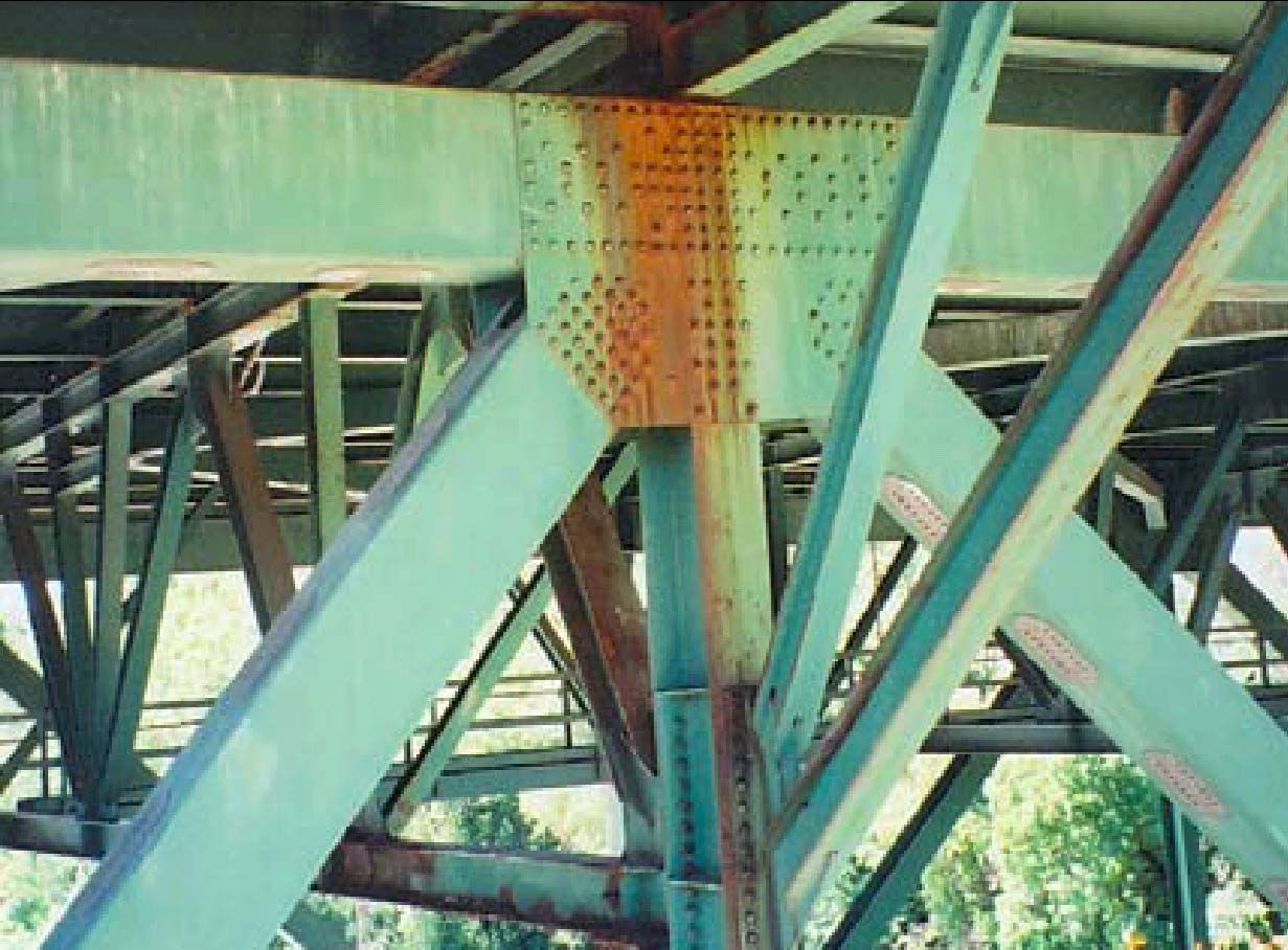
Not hard to imagine an L shaped fracture along those rust lines, and rivet lines, is it?
Which brings us to this question...
Why are the inspection reports word for word identical, even though they were conducted two years apart, over decades?
If the reports were cut and pasted, were the inspections themselves actually conducted? If the inspections were conducted, why didn't any inspectors ever comment on the obvious and unique coloration of the gusset which failed the bridge? The discoloration that precisely foretold the fracture line?
If any of our Minnesota Free Republic brothers and sisters can point a good Conservative newspaper to this post, perhaps they can ask these same questions publicly, and get answers, before any other skeletons come out of the closet by surprise, and kill some more bridge crossers.
45
posted on
01/16/2008 9:35:07 AM PST
by
jeffers
To: jeffers
46
posted on
01/16/2008 9:45:30 AM PST
by
The Mayor
( A man's heart plans his way, but the Lord directs his steps.—Proverbs 16:9)
To: jeffers
Most of that is over my head, but I know what this means:
Why are the inspection reports word for word identical, even though they were conducted two years apart, over decades?
47
posted on
01/16/2008 9:51:32 AM PST
by
Petronski
(Jeri Thompson is smarter than Mike Huckabee.)
To: jeffers
Thanks for the updated info and analysis.
At the time, I never had any question that the collapse was due to massive structural/design failure. Not being an engineer, and having never built a bridge, I could only speculate on what the exact cause was, but you have done a wonderful job explaining it.
At the time I remember that there were quite a few people around here who were bound and determined to call this an act of terrorism; while still tragic, I am happy that they were proven incorrect.
48
posted on
01/16/2008 9:52:31 AM PST
by
wagglebee
("A political party cannot be all things to all people." -- Ronald Reagan, 3/1/75)
To: Adder
The idea is that a structure stands for its rated life, during which time it is periodically imspected and maintained. After its rated life it is reevaluated to see if its life can be extended.
The whole idea is that a properly maintained structure, within its rated life, has a very small probability of catastrophic failure.
That it failed indicates that it either was not maintained properly or it was poorly designed.

Still Going Strong 124 Years On
To: Emperor Palpatine
Optical illusion, or are those pretty danged short wings on that bird?
50
posted on
01/16/2008 10:06:51 AM PST
by
Attention Surplus Disorder
(We've checked, and all your zeroes are OK. We're still working on your ones.)
To: B4Ranch; jeffers
Are there any before and after pictures of Pier 6?
I am interested in after pictures that show the entire structure of the pier.
Jeffers has again done an outstanding job of documenting the point of failure of the center span. His ability to document with pictures and expalanations are unmatched.
My gut instinct tells me that the failure of the center span at Gusset U10 was an event that had its beginning in a shift of Pier 6 towards the river due to scour or failure of the soil beneath the pier footings. The horizontal shift popped the entire bridge off of Pier 7, after the strain had built up to an intolerable level. Thus the approach to Pier 7 fell and a portion of the center span wound up on the side of the pier, rather than just failing downward. The horizontal shift towards Pier 7 also pulled the approach span off of Pier 6 as well, causing it to fall.
The bridge failed under a situation when it was nowhere near its design capacity—no ice, no snow, no wind, no eight lanes of bumper to bumper traffic, and no lessening of its factor of safety, and it was standing for 40 years.
The bridge fell so violently and so quickly that something foundationally was wrong. The result shows up in how the piers looked after the collapse.
I don’t doubt that Plate U10 failed, as the failure of any one plate would have brought the center span down. There were also fifteen other plates that showed a failed condition, no doubt a result of the collapse itself.
I may be all wet, but I recall a post collapse picture taken the evening of August 1st that showed that Pier 6 had moved. Pier 7 did not move at all, as it was locked in by concrete, whereas Pier 6 was in the water of the river.
I’m not a structural engineer like Jeffers, but something about the gusset plate theory doesn’t ring right to me as the only initiator of the entire event.
51
posted on
01/16/2008 10:22:39 AM PST
by
exit82
(How do you handle Hillary? You Huma her.)
To: jeffers
Thanks for the very interesting analysis! I will have to read it over a few times to digest all the info.
Where did you read that the inspection reports were identical?
To: bert; jdm
>>>>....architects returned to the more robust pre-war concepts....
>>If he can’t distinguish between an architect and a structural engineer one wonders if he knows the difference between his ass and a hole in the ground?
A reporter? A likely-innumerate reporter, reporting on a fairly technical subject?
No chance in h3!!.
53
posted on
01/16/2008 10:45:55 AM PST
by
FreedomPoster
(Guns themselves are fairly robust; their chief enemies are rust and politicians) (NRA)
To: jeffers
Thanks for the ping on this very important topic.
Thanks also for your exhaustive analysis.
The TV news (FWIW) is saying that the gusset plates should have been twice as thick. 1 inch thick versus 1/2” thick.
Also they said that the original calculations are “missing”.
Firstly the “missing” bit is an obvious cover-up because I’m sure that design was approved at the time it was built and re-approved dozens of times via inspections.
Technology does improve over time so why was there no incentive to improve or upgrade the bridge as we learn more about such structures.
Answer, Tombstone Technology - Don’t fix it until bodies fall from the sky.
54
posted on
01/16/2008 10:52:47 AM PST
by
Milwaukee_Guy
(Don't hit them between the eyes. Hit them right -in- the eyes!)
To: jeffers
Thanks for attention to this and the update!
To: jeffers
Can we do a quick scan to see how many bridge inspection reports are word-for-word identical from one inspection to the next?
56
posted on
01/16/2008 11:33:57 AM PST
by
Southack
(Media Bias means that Castro won't be punished for Cuban war crimes against Black Angolans in Africa)
To: Hacklehead
So what, Hellary has been standing for 60, but she has a thicker buttress.So what, Hellary has been standing for 60, but she has a thicker butt.
There, now it's fixed.
57
posted on
01/16/2008 12:18:10 PM PST
by
concretebob
(If liberals aren't traitors, their only defense at this point is they are incredibly stupid)
To: Hacklehead
Her thighness’ shank’s mare are legendary.
58
posted on
01/16/2008 12:24:48 PM PST
by
tioga
To: Lonesome in Massachussets; Adder; Petronski; jeffers
I don't think the total load at time of failure is being calculated.
IIRC that bridge was undergoing repair at the time of collapse, with live traffic loads.
The combination of static and dynamic loading is what caused this bridge to fail when it did.
Had no repairs been underway, I think this bridge would still be standing.
If traffic had been re-routed during repairs, I think the bridge would still be standing.
59
posted on
01/16/2008 12:24:49 PM PST
by
concretebob
(If liberals aren't traitors, their only defense at this point is they are incredibly stupid)
To: concretebob
Agree, that wasn’t the issue I was addressing...
The bridge failed because it was loaded far beyond its original design specification and no one bothered to check when they started repairing it.
Clearly, Bush’s fault.
Navigation: use the links below to view more comments.
first previous 1-20, 21-40, 41-60, 61-80 ... 101-117 next last
Disclaimer:
Opinions posted on Free Republic are those of the individual
posters and do not necessarily represent the opinion of Free Republic or its
management. All materials posted herein are protected by copyright law and the
exemption for fair use of copyrighted works.
FreeRepublic.com is powered by software copyright 2000-2008 John Robinson


