Skip to comments.
Minneapolis I-35W Bridge Collapse Failure Analysis
opinion
| 8-21-2007
| jeffers
Posted on 08/21/2007 3:20:52 PM PDT by jeffers
Minneapolis I-35 bridge collapse: Failure Analysis
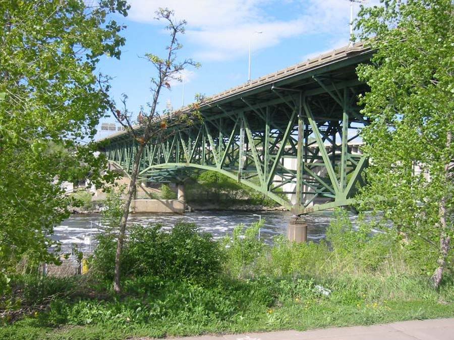
The I-35 West bridge over the Mississippi River in Minneapolis, Minnesota, consisted of three trussed spans and several beam and post spans typical of 1960's era freeway construction.
Analysis to date here at Free Republic has centered on looking for the triggering cause in the bridge collapse, and the sequence of failure, as determined by available pre- and post-collapse imagery and video.
Efforts so far have been hampered by uncertainty regarding the condition and disposition of the eastern truss panels originally located above and near pier 6. I hope to rectify this uncertainty and shed significant new light into the bridge's failure sequence in this analysis.
Per the 2006 MnDOT Inspection Report, the bridge's piers are numbered south to north, with the bridge's span's also numbered south to north. Since the southern approach begins with the south abutment, pier 1 is situated at the north end of span 1, and at the south end of span two. I will use the same referencing convention throughout this discussion. The full report, and numerous others, are available at:
http://www.dot.state.mn.us/i35wbridge/history.html
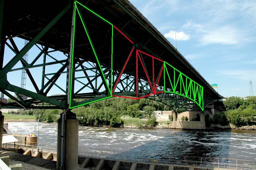
For reference purposes throughout this analysis, here is an image of the bridge prior to collapse, looking northeast, with pier six at center right foreground, span 7 over the river centered, span 8 visible at left, and part of span 6 visible at right:
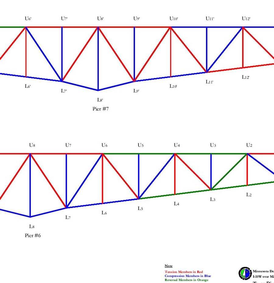
For additional reference, the image below shows the MnDot scheme of truss component identification, used thoughout this analysis:
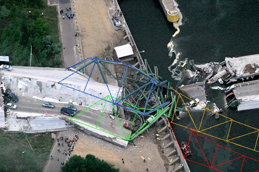
Early analysis, almost from day one after the collapse, noted that the western truss panels at pier six had rotated to the east on failure, and appeared to retain most, if not all, of their original structural integrity. Later examination indicated that the west truss panels at pier 6 probably separated, partially or fully, from the rest of span 7 prior to this eastward rotation, since the larger part of span 7 did not follow the main trusses east in rotation, as shown below:
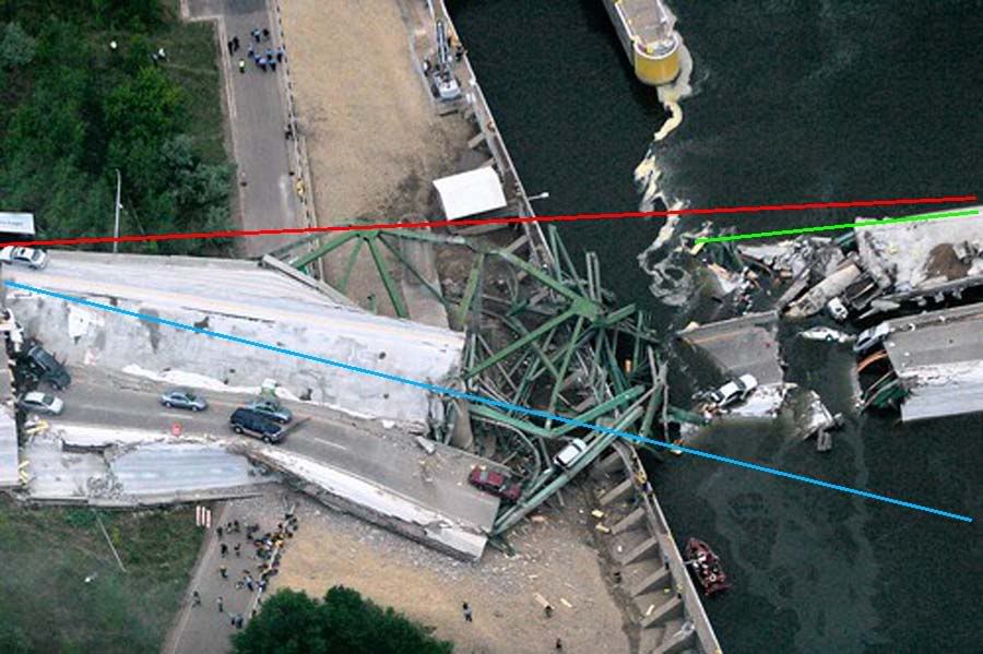
In the above image, the red line indicates the general orientation of the west truss prior to collapse. The blue line indicates the post collapse disposition of the pier 6 panels of the west truss, and the green line indicates the post collapse disposition of the main portion of the span 7 west truss. It is clear from this image that the two post collapse portions of the west truss are unlikely to have dropped while still attached to each other during all phases of the collapse sequence, and that separation probably occurred prior to the pier 6 west truss panels rotation to the east.
At this point in the investigation, suspicion was directed towards the east truss at and just north of pier 6, including, but not limited to the southeast pier 6 kingpost, one of four primary support members for the entire trussed spans. Without knowing the location or disposition of the pier 6 east truss members after the collapse, all such analysis was limited to supposition and speculation.
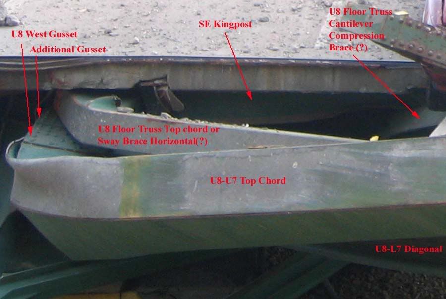
Additional research of the available imagery, however, was able to locate several of the east trusses' significant structural members, as illustrated and discussed below:
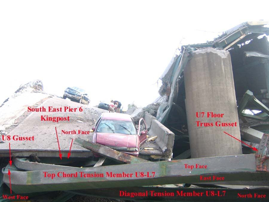
The key to discovery of the post collapse east truss components was the double gusset just visible in the above image, looking south towards the northbound traffic lanes at pier 6. This is typical construction technique, and had been noted in several pre-collapse images of the bridge. On discovery of the double gusset, additional members were located simply by following known east truss members to the next logical attachment points. A digitally enhanced zoom of the above image, clearly showing the doubled U8 connection gussets is shown below:
In the following image, looking west at pier 6, known east truss components are indicated in red, and these are used to identify post collapse east truss members indicated in green.
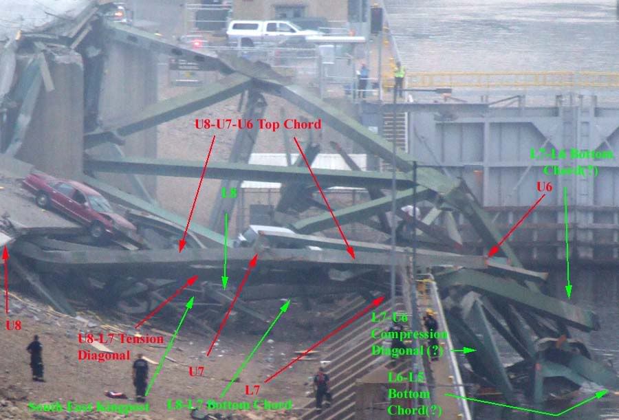
Important aside, note the post collapse disposition of the west truss member corresponding to east truss member L7-L6 in the above image, unmarked but located directly behind the red arrowhead labelled U6. Note particularly the attachment point L7 gussets and damage suffered by the west truss bottom chord in relation to the intact west truss panels, this will be referred to later in this discussion.
Image 6 below, looking west at pier 6 but closer than Image 5 above, add the post collapse location of a critical bridge component, part of the pier 6 east truss roller nest assembly.
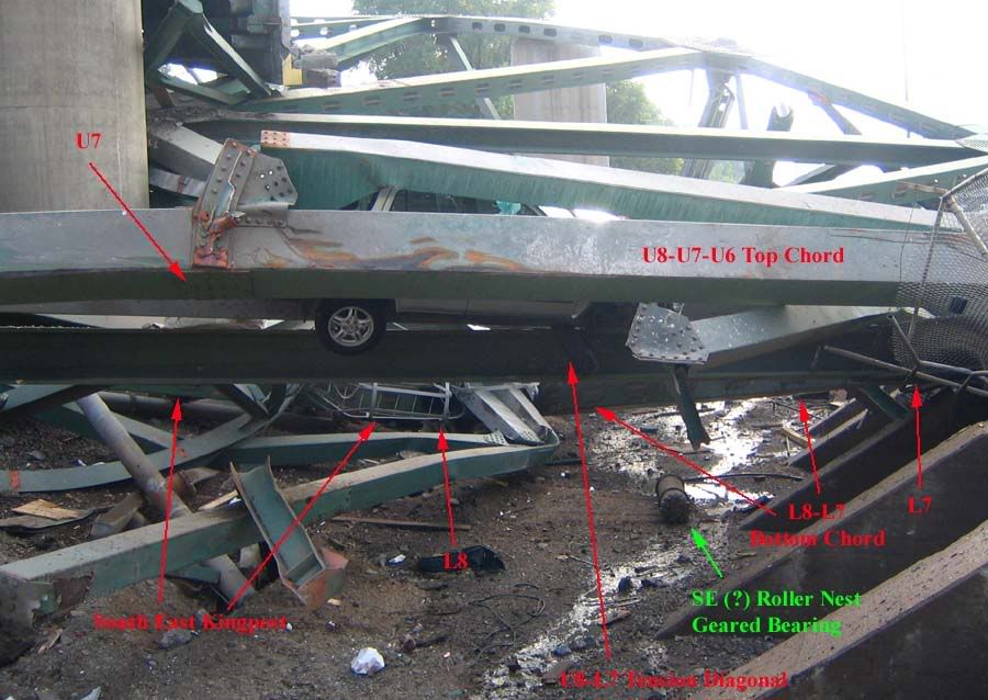
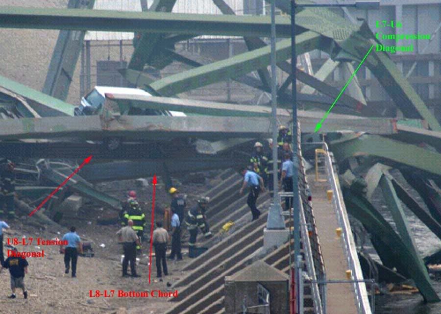
Image 7 below, also looking west at pier 6, notes the probable post collapse disposition of the L7-U6 east truss compression diagonal, or better put, the remnant stub thereof. Also visible in this image, behind the red U8-L7 arrow, is another critical pier 6 component, the southeast rocker bearing plate.
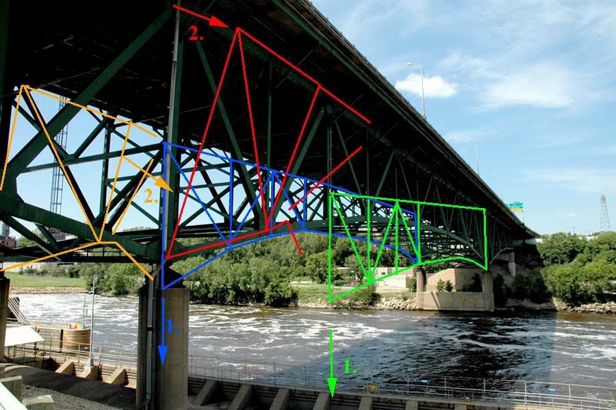
While the above images may be difficult for non-engineers to understand, they are important in establishing a basis for the following image, a post collapse diagram of both main trusses as oriented after the failure sequence was complete.
In image 8 above, looking down on pier 6, the known and likely locations of west truss pier 6 components are indicated in blue. The orange lines indicate the "missing" or severed members of the west truss further out into span 7, as they would have appeared had span 7 not severed early in the collapse progression.
Similarly, known or likely locations for east truss pier 6 components are indicated in green, while extensions of same without span 7 separation are indicated in red. These lines were constructed atop the base layer imagery on separate Photoshop image layers, to facilitate construction of the following image, where by the layers are lifted from the previous sub-image layer, rotated and re-oriented to pre-collapse dispositions, for comparison purposes.
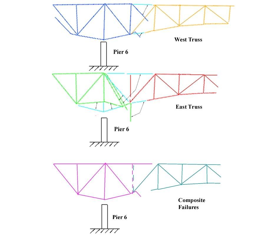
In the above image, Image 9, looking west at pier 6, the two upper panels indicate the west and east trusses, as reconstructed from post collapse imagery, respectively. The blue lines indicate the original positions of members which were located in post collapse imagery, and rotated back into the pre-collapse dispositions.
The lower panel in Image 9 notes the combined post collapse arrangement of both the east and west truss for comparison purposes, and the similarities are striking. With the exception of the U7-L7 strut, the first vertical truss member north of the pier 6 kingposts, both trusses apparantly failed in near identical manner. Noteworthy points of similarity include the U7-U6 top chord severance locations near the U6 connection gusset, the bending moments impressed on both east and west U7-U6 top chord members, the severance locations of both east and west truss L7-L6 bottom chord members, and the bendimg moments impressed on same, and the catastrophic failure at the west truss L7 gusset, specifically the tension and bending loads imposed on the L7-U6 compression diagonal mentioned earlier, which coincide with the apparant severe moments imposed on the east truss's coincident member.
So far, the discussion here has been limited to empirical evidence and my interpretation of same. This is as far as my analysis allows me to proceed without supposition and speculation, however, I am reasonably confident that additional analysis is at least within the bounds of probability and possibility regarding the failure of this bridge.
Put another way, the conclusions I am about to draw cannot, as yet, be substantiated in fact, but neither can they be refuted by the evidence availabe to us at this time. They are well within the realm of structural possibilities as we now know them.
From all analysis to date, we have reason to believe that:
1. Most of span 7 separated from the span 7 pier 6 truss panels prior to east rotation of the pier six truss panels.
2. Video analysis of the failure sequence shows the south end of the bridge falling earlier than the north end of span 7.
3. The east truss at pier 6 mosdt likely lies underneath the west truss at pier 6.
With the benefit of newly discovered data as outlined in this discussion, I offer the following tenative, additional conclusions.
1. Both east and west truss L7-U6 compression diagonals were subjected to severe tensile and bending stresses and shattered near the L7 connection gusset.
2. Both east and west truss U7-U6 top chords were subjected to tensile stresses at or above failure levels early in the collapse progression resulting in separation at or near the U6 connection gusset.
3. Both east and west truss L7-L6 bottom chords were subjected to severe stresses at or near the L6 connection gusset, and both were subjected to bending moments consistent with failure level gravity loads about the L7 connection gusset.
Based on these tenative additional comculsions, I believe it most likely that the east truss U7-U6 top chord failed in tension at or near the U6 connection gusset very early in the collapse progression, quite possibly as the collapse sequence initiating event.
If in fact this key structural member failed as discussed above, a progressive collapse sequence could ensue as follows:
With the east truss top chord severed at U6 as shown in Image 10 above, externally imposed tension loads on U7-U6 go to zero, while internal stress on this member predominates. The upper face of this box beam goes into radical tension while the lower face goes into compression, inducing a bending moment at connection U7, 100% consistent with the post collpase disposition of this member. A similar progression is imposed on the L7-U6 compression diagonal.
Both live and dead span 7 gravity loads are almost immediately transferred to the east truss L7-L6 bottom chord, imposing internal stress on that member similar to that discussed above. It cannot resist the imposed stresses and begins to deflect downwards, as shown in Image 10 above and also indicated by red arrow 1 in Image 11 below.
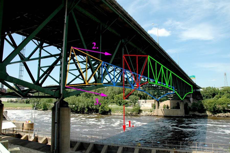
As soon as the east truss L7-L6-L5 bottom chord begins to deflect downwards, significant tensile loads are applied to the horizontal and diagonal sway bracing members at the U6-L6 interface, as indicated by orange arrows 2 and 3 in Image 11 above. These tensile stresses are transferred to west truss members at the swy brace connection points, and are resisted by the both the west truss roller nest/rocker bearing assempbly atop pier 6, and by sway bracing in the horizontal planes co-planar with the west truss top and bottom chords. The vector pair of eaastward tensile stress, and westward resistance to same induces an eastward rotational moment about the west truss bottom chord, transverse (laterally) to its axis.
This rotational moment of the west truss top chord towards the east is transmitted to the now separated pier 6 panels of the east truss via the much more substantial sway bracing atop pier 6 as shown below, by red and orange arrows 2., in Image 12. Both the southwest and southeast kingposts at pier 6 are now in rotation to the east. The main portion of span 7, no longer attached at the east truss top chord, and probably not at the west truss top chord, is subject to much less eastward deflection, by virtue of their bottom chord only attachments to the rotating pier 6 superstructure, however, this rotation imposes severe twisting stresses on both the east and west L7-L6 bottom chord members, again 100% consistent with post collapse imagery data.
Not too far into the rotational failure of the pier 6 superstructure, both bottom chords separate at the L6 connection gussets, and once unsupported at their midspan ends, are nearly severed or completely severed at the L7 connection gusset, 100% consistent with post collapse imagery.
From here, the collapse progression holds little surprise or ambiguity. The pier 6 superstructure continues to rotate eastward, and the rest of span 7's trusswork and road deck, severed from the pier 6 truss panels and unsupported at their south ends, drop straight down into the river. At some point during the sequence, span 6, south of pier 6, having lost the counterbalancing weight associated with the span 7 cantilever compenent, begins to deflect downwards, sagging at midspan, and inducing a smaller but significant rotation to the pier 6 superstructure. This induces the tops of the pier 6 kingposts to rotate a small distance to the south, resisted by the pier 6 roller nest assembl;ies and rocker bearings, and ejects the pier 6 roller nest and rocker bearing components northward from their pro-collapse positions atop pier 6, consistant with their post collapse disposition as evidenced by the available imagery.
Finally, I would repeat that while I cannot prove this is the correct failure sequence, I can say that this sequence is consistent with all available data of which I am aware, and that none of the available data contradicts these assumptions, conclusions and speculations to any appreciable extent of which I am aware. More as new information or imagery becomes available.
Feel free to distribute this analysis for any non-commercial purposes, though I do ask that Free Republic be referenced in all such distributions. All imagery used in this analysis was accessed in the public domain, though original copyrights still reside with the original owners or their designees. Overlying graphics analysis may be distributed for non-profit purposes, with Free Republic referencing as outlined above.
I greatly appreciate all who have contributed to previous discussions regarding this matter, you are too numerous to name but you know who you are. Without your efforts in analyzing this failure, and in bringing imagery and video to my attention, none of this discussion would have been possible.
Thank you.
TOPICS: US: Minnesota; Your Opinion/Questions
KEYWORDS: 35w; analysis; bridge; bridgecollapse; collapse; disaster; engineering; highways; i35; minneapolis
Navigation: use the links below to view more comments.
first previous 1-20, 21-40, 41-60, 61-79 last
To: kwuntongchai
Your piers are labelled correctly, but not your connection points.
The mainspan (span 7) center vertical strut is member U1-L1. The next strut south of there is U2-L2. The next strut north of the center strut is U2’-L2’.
Your cantilevers and trusses are generally correct, but the two center cantilevers are drawn a little generous. In the proper labelling scheme, the pier 6 cantilever only extends out (towards midspan 7) to U6-L5.
I’ve looked very hard at a triggering failure in the southern approach. Over and over again, I have to rule it out, at least as the most likely sequence.
Primary reason, as you note, the pier 6 superstructure would have rotated, top towards the south, if span 6 sagged midspan. That would have lifted the south end of span 7 well up above the horizontal plane of the deck, and we simply do not see this in the video.
If it happened that way, the top chord fractured north of pier 6 almost immediately, before any (assumed) visible deflection took place in span 6, and before said deflection could induce (actual) visible elevation of the span 7 south end.
I won’t rule out a triggering failure at the pier 5 crossbeam/endbeam rocker assembly, given the history there.
But the video does not visibly support such a sequence, and therefore, it’s not the first sequence in my assessment of the likeliest possibilities.
61
posted on
08/22/2007 8:37:21 AM PDT
by
jeffers
To: All; kristinn
Hey, Bill O'Reilly.....get your sorry eyeballs over to this thread and tell your audience once again that Free Republic is a "hate site" populated by knuckle-dragging neanderthals.
Leni
62
posted on
08/22/2007 8:47:45 AM PDT
by
MinuteGal
(Three Cheers for the FRed, White and Blue !)
To: kwuntongchai
It’s not the best image I’ve seen but you’re looking at the south endbeam in this photo.
The junction between the south end of the main trusses and normal beam and post approach spans did not fall directly over pier 5. It was located south of pier 5, and was designed as a somewhat complex cantilever assembly.
The far end of the beams you see (resting on the ground) were between pier 4 (seen in the image) and pier 5, (not seen).
For illustration as to why the visible beams buckled to the near side of the visible pier 4, imagine pier 3, pier 4, no main trusses, and no pier 5.
In such a scenario, the visible beams sit with one end on pier 3, and are cantilevered out into free space past pier 4. Load the free end of the cantilever in excess of design limits, and yes, the beams will buckle just to the pier 3 side of pier 4, as you see in the image.
That is where the bending stresses reach maxima. The reason for this is due to the lifting reaction placed on the pier 3 end of the beams. If the only stress in play was the gravity load on the free end of the cantilever, then the beams would buckle over pier 4. But the dead load and connection assemblies at pier 3 resist the gravity load imposed on the free cantilever, and in effect, bend the beams over pier 4 like a fulcrum.
There’s more to this, involving the nature of the pier 4 beam connections and how they are permitted to move and restricted in movement, but this should outline the basic idea.
63
posted on
08/22/2007 8:51:38 AM PDT
by
jeffers
To: jeffers
64
posted on
08/22/2007 11:52:19 AM PDT
by
BlueMondaySkipper
(The quickest way of ending a war is to lose it. - George Orwell)
To: jeffers
I have seen claims that materials and heavy equipment were stored on the bridge, but I can’t say I’ve seen proof of this. Would telling you that I saw the equipment sitting on the bridge a couple of times a day when I crossed it during June and July substantiate the claims?
65
posted on
08/22/2007 3:12:15 PM PDT
by
DrDavid
(Is this a rhetorical question?)
To: DrDavid
Yep.
Can you remember what you saw, and where it was?
Especially interested in heavy loads between mid span 7 and just south of pier 6.
66
posted on
08/22/2007 3:37:25 PM PDT
by
jeffers
To: jeffers
In the deck repairs underway, does anyone know what was being done.
Removal could have had small cushman type debris removal staged to another point on the bridge and then hi-loadered into dump trucks. Cushman’s wouldn't’t be a big load nor would small piles of debris staged for reloading. Only one truck would have been filled at a time and then it would depart. Others waiting would have been empty, not full as some have speculated in discussing “trucks full of gravel”
In the repaving operation, if concrete, we could have seen ready-mix trucks lined up too far out on the structure and a paving screed. I haven’t heard there were ready-mix trucks in the collapse debris vehicles.
Conversely, if asphaltic paving or wear course was underway, a “paving train” would have consisted of a crawler driven small paving machine and trucks loaded with heavy asphalt lined up to dump in it. These heavy trucks could have been staged off the structure or they could have lined up on the closed lanes.
It appeared that small sections were being done in stages so I don’t really think that any of the foregoing were the case, but there has been so much talk of construction material loads that at least we should discuss what we might be looking for in the debris or observations.
I can imagine that MDOT and the contractor aren't talking about specifics at all until the forensics and formal investigations are done.
I can imagine that the contractor and his liability carrier as sweating blood.
67
posted on
08/23/2007 7:13:06 AM PDT
by
KC Burke
(Men of intemperate minds can never be free...their passions forge their fetters.)
To: KC Burke
Something I noticed studying the images, was that the roughened deck surface visible after the collapse appeared to be confined to the SW corner of the bridge, maybe from pier 5 and south, in the southbound lanes.
I imagine the contractor had an overall schedule, and other parts of the contract work could have been underway elsewhere, but that corner seemed top be the primary focus of work in progress from what the post collapse imagery showed.
68
posted on
08/23/2007 7:23:57 AM PDT
by
jeffers
To: jeffers
Then it seems to have appeared to have been a scarify and re-surface type of repair if roughened pavement is what was seen.
With that type of repair it can have a new surface in either concrete topping or asphaltic topping depending upon the substrate of the paving. Both operations can either be done in small segments or in large scale paving operations as previously described.
In either topping we are not looking for "trucks loaded with gravel" as some news accounts describe, but instead, we are looking for trucks loaded with hot asphalt or ready-mix trucks. The former would have been servicing a paving machine: 
The machine and the trucks servicing it should have been smaller that what is shown above but this shows the operation and machinery type.
A concrete paving operation could have been a small vibrating screed with almost no weight or something of this type

Again, this is a larger unit that what would be used for bridge topping but it shows the sort of machine utilized and its appearance for those not familiar with this process.
69
posted on
08/23/2007 7:52:18 AM PDT
by
KC Burke
(Men of intemperate minds can never be free...their passions forge their fetters.)
To: jeffers
Can you remember what you saw, and where it was? From what I remember is they had what I think they were generators built on trailers, trucks that came and went and road cutting saws. There were several of each of these distributed the full length of the bridge on both sides. They took up a lot of the 2 outside lanes in both direction, where they were working.
This is kind of vague, but hopefully it is helpful.
70
posted on
08/23/2007 10:27:59 AM PDT
by
DrDavid
(Is this a rhetorical question?)
To: DrDavid; jeffers
I would think that the truck mounted items you saw were truck mounted air-compressors as opposed to generators.
Compressed air generators and the trucks are not heavy virbration or dead load.
Compressed air is used to blow off the light debris and dust after the larger chips are removed behind any scafication operation. That gives a clean surface that the topping / resurfacing can bond to as it is placed.
71
posted on
08/23/2007 1:02:55 PM PDT
by
KC Burke
(Men of intemperate minds can never be free...their passions forge their fetters.)
To: jeffers
Very nicely done. You made one mistake, though, which confuses me as I read your analysis. The naming conventions you've adopted regarding the location of the panel points (U6, L7, U8, etc.) are not the "official" ones. I think you got confused by page 50 of the June 2006 Fracture-Critical Inspection report. That diagram is missing the legend that says the observer's point-of-view is upstream, i.e. to the
west of the bridge looking east. In the diagram you posted, south is to the right, not the left as you assume. U8/L8
is still correct, above Pier 6 on the south end of the bridge. Most of the Pier 6 photos in your article were taken by photographers situated to the
east of the bridge looking west toward Pier 6. This is nominally a "downstream" view.
So you've got it semi-backwards. What you refer to as U7/L7 and U6/L6 are actually U9/L9 and U10/L10 according to all the official documents available regarding the bridge. The panel point numbers increase as you head north from Pier 6 out over the river. The center point of the bridge is at U14/L14. The southernmost point of the main deck trusses is U0 (there is no L0 or L28 at the "points of the cantilevers), and the numbering increases from south to north. Since there is symmetry about the center there is also the convention of referring to the points north of U/L14 as U13' to U0', in descending order as you head north. Pier 5 (south of Pier 6) supports the south end of the structure at L1, and Pier 8 (north of Pier 7) supports the north end at L1' (also referred to as L27 in various documents). The main numbering sequence increases from south to north whereas the "prime" sequence increases from north to south.
This in no way invalidates your analysis since we're only talking about the labels of different points on the structure. It just confuses me greatly to have to make the extra transposition in my head when reading your article. Please have a look at page 48 in the June 2005 Fracture-Critical Inspection report and it should become clear to you. That is the correct orientation of the panel points when looking at the bridge (or what remains of it) from a position to the east (downstream). The diagram you used at the beginning is the upstream view. Things being symmetrical makes it easy to get confused. It took me a week to understand which panel points were which.
OK, on to another couple of points...
The guy on the bicycle who is seen in many pictures from 1 August is a real hero and yet his story is almost completely unknown. He just climbed up there on the roadway rubble pile and helped about 10 people to safety. Unsung doesn't begin to describe
Dan Schueller's courage that day. He didn't waste any time and he's no spring chicken either. I wish there was more news coverage of what he did. I like to think I would have done the same thing, but man, that had to be terrifying to see that happen while you're out riding your bicycle. Schueller was maybe the first person on the scene who wasn't in the collapse event itself.
In response to those who suggest the Army Corps of Engineers' security videotape was edited, I think it's likely the camera works only when it detects motion in its field of view. That would explain a lot of the gaps in it. Notice how after the initial collapse it kicks in again after a gap when it "sees" span 8 on the north side begin to tip over backwards, and again when the woman with the cell phone runs by. At the start of the tape it probably activated just after it detected the initial motion of the center span. I doubt there was anything edited on the tape. IMO there was nothing recorded before then, although I have no way to know for sure. I
do know for a fact that there are security video systems out there that use motion detectors for activation.
Speaking of that video, who
was that woman, anyway? She must have been standing only a few yards from where the bridge came down. She's lucky it didn't shift to the north instead of the south. I'm sure the authorities found her and interviewed her as a key eyewitness.
Finally, I want to post a sample of a 3D rendering I did from a quick CAD model of the bridge I made (like you, jeffers, I'm probably spending way too much time on this). My goal is to recreate the field-of-view of the ACE security camera. So far I'm not pleased with the results. Being a security camera, it probably had a fisheye lens. My software is too primitive to handle that, but I'm still searching for a solution.

I can't figure out the "hump" on the roadway as you go north. Maybe that's why I want to believe the camera had a fisheye lens that distorted the image somewhat. The north end of the roadway around Pier 7 is several feet below the roadway at Pier 6 and I first thought that was why it looks curved. The model I made is pretty accurate so I don't think that explains it. I guess it's time to add the roadway to the model.
Like I said, good work, jeffers. I've been searching for somewhere on the web where people are discussing the 35W collapse and there aren't too many. There were a lot the first week after it happened, but most of the discussion has died down since then. I think there are alternative explanations for the failure sequence but yours is definitely on the short list of finalists. I'm like you: I'm too impatient to wait for the official NTSB report which we might not get for more than a year.
That's it for now.
72
posted on
08/27/2007 4:39:52 AM PDT
by
mroper
To: mroper
Regarding the official bridge labelling scheme, you are correct. The drawing I based my assumptions on is a poor one but the text, on deeper investigation, does indicate the correct labelling scheme, and I apologize for any confusion in this area.
I also note that an earlier poster’s scheme actually is correct.
I pity the efforts you had to go through to make sense of my analysis in this respect. It’s hard enough to understand when the numbers line up.
As you note, a different scheme doesn’t change the basic conclusions, though I would clearly state, it moves the suspected problem area to the U10 connection point of the east truss.
This opens the door for some new data, and I am still working on other areas of analysis, including construction traffic and further identification of structural members in post collapse imagery.
I doubt these avenues of analysis will lead to concrete conclusions, and have to decide whether to publish sheer speculation or let important, but unresolved, issues lie unmentioned.
I note with interest your assessment that other scenarios are possible. I have looked at some of these, and for the most part, found one or more conflicting datapoints that appear to rule them out, though U have not and will not do so categorically.
I’d be interested in your read of other failure mechanisms that remain possible, given the available pool of empirical evidence.
I believe that posting them, even as speculation, yields more benefit then harm, and opens the door for further discussion.
73
posted on
08/28/2007 6:42:48 AM PDT
by
jeffers
To: jeffers
Thanks for responding. I was afraid everyone had finally left this discussion! I think it’s important to realize there is a line between what we know or can logically infer, and rank speculation. As long as we maintain an awareness of that distinction I think it’s reasonable to postulate and conjecture.
Your fine detective work on identifying the steel members of the structure post-collapse is 100% valid IMO. It may be too much to ask that we’ll see hi-res pictures of the scene as the rubble is removed. I would think they would remove the concrete and rebar first, exposing the steel underneath. There’s a lot under there we’ll never see.
Regarding alternative collapse sequences, my thoughts on that come from reading the URS bridge analysis report. They identified 52 critical beams that, if one of them failed, would cause others to fail like dominoes. They listed them in their report but I need to go back and read it again. IIRC they identified secondary failures in some members that were not in close proximity to the initial failed member. That stood out when I first read it and I must read it again. Their study, of course, is predicated on certain assumptions that may turn out to be invalid. Garbage in, garbage out. If there initial data was bad then the results are suspect.
My model is not a finite-element model. It’s visual only so right now I don’t envision plugging it into any stress analysis software to analyze. Speaking of the picture I posted above, it occurs to me that perhaps the deck had already begun to fall in the first frame of that video. That could potentially explain the “curvature” of the roadway that I cannot replicate with the intact model. And speaking of video, I read yesterday that someone thought the camera wasn’t a video camera at all, but rather one that snaps still pictures in sequence, either at timed intervals or triggered by motion detectors. I don’t want to speculate further on that without knowing more about the actual camera system they use.
Glad you’re still here.
74
posted on
08/28/2007 1:33:54 PM PDT
by
mroper
To: jeffers
Following are the individual frames of the Army Corps of Engineers video of the I-35W bridge collapse, which all may find of interest.
There are a total of 26 frames of video, and in the original (posted) sequence it lasts a total of about 12.4 seconds, meaning that the time between frames is about 0.477 seconds.
It is interesting to note that there is no bridge movement between the first and second frames, meaning that the video has captured the entire collapse from the start (which begins between frames 2 and 3, and is already underway at frame 3. It is also interesting to note that there is a very slight upward shift of the camera between frames 2 and 3 (coincident with the beginning of the collapse).
It is also noteworthy that the bridge segments closest to the camera (at least from initial observation) appear to be falling straight down. It is difficult from this perspective to tell if the east (far) side of the bridge was falling ahead of the west (near) side.
Even though the bridge appears to have broken somewhere on the south end, out of camera view, these pictures can perhaps still provide some additional information and insight into the collapse.
Bridge00.gif
Bridge01.gif
Bridge02.gif
Bridge03.gif
Bridge04.gif
Bridge05.gif
Bridge06.gif
Bridge07.gif
Bridge08.gif
Bridge09.gif
Bridge10.gif
Bridge11.gif
Bridge12.gif
Bridge13.gif
Bridge14.gif
Bridge15.gif
Bridge16.gif
Bridge17.gif
Bridge18.gif
Bridge19.gif
Bridge20.gif
Bridge21.gif
Bridge22.gif
Bridge23.gif
Bridge24.gif
Bridge25.gif
75
posted on
08/31/2007 10:53:47 AM PDT
by
sgw1009
To: sgw1009
I downloaded those as soon as I got your e-mail.
Those and the other images you linked me to are very good ones, and have already allowed me to further the investigation.
Some things are becoming very clear, expect some minor changes in my opinion of where the earliest known failure occurred, but nothing major.
I’m going to take a few of those video images and manually extend the superstructure skeleton to the right to include pier 6 and you’ll see what I mean.
The focus is narrowing and the possibilities diminishing, and there are critical superstructure elements visible in both the older images, and to a better degree in the newer ones.
It will take time to put it all together, and I am obligated over the weekend elsewhere. Maybe mid next week?
In any event, thanks for your help with those images, your contribution to our informal analysis cannot be overstated.
76
posted on
08/31/2007 12:08:47 PM PDT
by
jeffers
To: jeffers
Hi Everyone,
I’ve been away for a couple weeks, are there any current discussions on the collapse? How about current images from the debris cleanup?
Kwuntongchai
To: kwuntongchai
78
posted on
10/05/2007 9:00:02 PM PDT
by
Orion78
(Only a slave can work with no right to the product of his effort.)
To: jeffers
From
USA Today ^ is a report from the NTSB blaming the gusset plates; used 1/2-inch thick as against 1-inch thick. Seems they didn't fully account for the increase of road lanes from four to eight against the original design weight loading:
Design changes in 1977 and 1998 added additional pavement and concrete barriers that increased the weight of the Interstate 35W bridge in downtown Minneapolis.
Thank you for your info above.
79
posted on
01/15/2008 1:21:38 PM PST
by
brityank
(The more I learn about the Constitution, the more I realise this Government is UNconstitutional !!)
Navigation: use the links below to view more comments.
first previous 1-20, 21-40, 41-60, 61-79 last
Disclaimer:
Opinions posted on Free Republic are those of the individual
posters and do not necessarily represent the opinion of Free Republic or its
management. All materials posted herein are protected by copyright law and the
exemption for fair use of copyrighted works.
FreeRepublic.com is powered by software copyright 2000-2008 John Robinson