You may find this #268 of interest.
WELLLLLL FRIENDS, Here's some interesting links related to the earlier long post. I'm in the process of verifying particularly some of the zero point energy docs' links and posting some of the intros and interesting graphics from those docs. Blessings,
The following doc is found at:
http://jnaudin.free.fr/
THIS SITE INTROD BELOW IS REACHABLE—at the moment—at the link above:
Dear new explorers and experimenters,
You are WELCOME in the JLN Labs web site dedicated to the search of Free-Energy solutions and new generation of space-propulsion systems.
Good exploration,
Jean-Louis Naudin ( France )
If we could produce electric effects of the required quality, this whole planet and the conditions of existence on it could be transformed. The sun raises the water of the oceans and winds drive it to distant regions where it remains in state of most delicate balance. If it were in our power to upset it when and wherever desired, this mighty life-sustaining stream could be at will controlled. We could irrigate arid deserts, create lakes and rivers and provide motive power in unlimited amount. This would be the most efficient way of harnesing the sun to the uses of man......" ( Nikola Tesla, June 1919 )
The ElectroHydroDynamics ( EHD) may open new ways in advanced propulsion. An EHD device uses a direct conversion of electrical energy into kinetic energy. A specially shaped electrostatic field creates an hydrostatic pressure (or motion) in dielectric media. If the media is a fluid like air (or aether), a flow is produced and this produces a motion of the device. A powered flow of medium (like air or Aether) within a shaped electrostatic field adds energy to the system which is picked up (as potential difference) by electrodes and thus produces energy.
This link:
http://jnaudin.free.fr/html/lifters.htm
IS introduced this way:
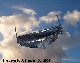 The Lifter is an asymmetrical capacitor which uses High Voltage ( > 20KV ) to produce a thrust.
The Lifter works without moving parts, flies silently, uses only electrical energy and is able to lift its own weight plus an additional payload. The Lifter uses the Biefeld-Brown effect discovered by Thomas Townsend Brown in 1928. The basic design of the Lifter has been fully described in the Townsend Brown US Patent N°2949550 filed on Aug 16, 1960 and titled "Elektrokinetic Apparatus", you will find in this patent the full description of the main principle used in the Lifter devices.
An aircraft equipped with an electrokinetic system of propulsion based on the system of Townsend Brown has many very interesting characteristics, like :
- Vertical Take Off and Landing (VTOL) capabilities,
- a reduced aerodynamic drag,
- an increase in its flight time and thus in its operating range,
- an absence of mobile control surfaces (ailerons, rudder, elevator ) and thus no reflective mobile surface to the radar waves,
- a high maneuvrability (an adaptive flight envelope ) due to an intelligent control of the laminar flow,
- a full silent flight,
- a quasi null thermal signature,
- the use of an electric power generator and thus no fuel is required,
- the electromagnetic waves scattering and stealth capabilities...
-
-
-  -
-
- THE 194G Lifter “Maximus” with 60 g of payload -
-  -
-
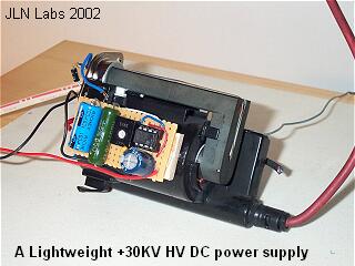
- Lightweight power supply for lifter. -
-  -
-
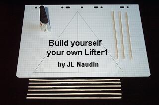
- Build yourself your own Lifter1. -
-  -
-
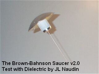
- The Brown-Bahnson Saucer v2.0 -
-  -
-
- A Proposed Electrodynamic Thrusting Mechanism by Charles A Yost -
-  -
-
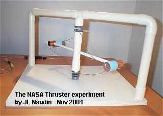
- The NASA Two Dimensional Asymmetrical Capacitor Thruster -
-  -
-
- The NASA Orbital Maneuvering Propellantless Thruster v1.0 -
-  -
-
- The Serrano’s Field Propulsion Thruster v1.0 -
- ============================================
- END OF THE LINKS AND SAMPLING OF INTERESTING PICS FROM ABOVE DOCUMENT
- ===========================
-
- 2ND DOC BELOW FOUND AT: -
- http://jnaudin.free.fr/html/tbfrenrg.htm -
- IS INTRO’D THIS WAY: -
In the paper " The Final Secret of Free Energy " wrote in February 9, 1993, Tom Bearden has described the principle of a device which seems able to tap Free Energy from the energy flow ( the Poynting S-Flow ) in the vaccum during the short transient phase ( the relaxation time in a conductor ) when a source is connected to a resistive load. In this paper, I am trying to clarify a bit, the basic concept of this principle.
Tom Bearden claims that when a Source ( a dipole ) is connected to a resistive load, the most important part of the principle is the information transfered to the load at the speed of light by the S-Flow. The S-Flow is pure EM energy which flows through the space and outside the conductor. This energy is Free and only this part must be used as a "free lunch". Just after this very short time, after that the switch is closed ( the transient phase ), the current begins to flow in the circuit. This transient phase is named the Relaxation Time. In copper, the relaxation time is incredibly rapid, it's about 1.5 x 10⁻¹⁹ sec. When the current flows ( the permanent phase ), the circuit consumes power from the Source and dissipates energy by Joule's Effet, this phase must not be used in our case.
So, according to Tom Bearden, for tapping Free Energy, the purpose is to charge a " Collector " during its relaxation time and then, to switch this Collector to a common resistive load, just before that the electrons begin to flow in the circuit.
We took some trapped EM energy density (a chunk of potential gradient, a "voltage" before current flows) from the source, by switching that potential gradient (energy density, which is joules per coulomb) onto a collector (containing a certain number of coulombs of trapped charges) where the potential gradient activates/potentializes/couples-to these temporarily non translating electrons. So the finite collector collected a finite amount of excess energy [joules/coulomb x collecting (trapped) coulombs] on its now-excited (activated) free electrons. Then, before any current has yet flowed from the source, we switched that potentialized collector (with its temporarily restrained but potentialized electrons; with their finite amount of excess trapped EM energy) away from the source and directly across the load. Shortly thereafter, the relaxation time in the collector expires. The potentialized electrons in the collector are freed to move in the external load circuit, consisting of the collector and the load, and so they do so. -- has said Tom Bearden.
For the Collector it is necessary to use a conductive material which has a longer relaxation time than in the copper. This is only for the electronic circuit design and the limitation of its components. So, Tom Bearden has used " a Degenerate Semiconductor " which has a relaxation time of about 1 ms. The Collector is made with 98% Aluminum and 2% Iron.
THE following interesting graphic is in the document sourced at the above link:
“The Bearden’s Free Energy Generator principle – Animation by JL Naudin . . . “
I hope to get some more links verified and their introductions included with the links in another posting or two later this evening.
Blessings,
Q
2ND PART OF VERIFIED DOC LINKS AND INTROS:
http://www.cheniere.org/techpapers/Final%20Secret%2013%20May%201994/index.html
PRACTICAL OVERUNITY ELECTRICAL DEVICES
(C) T.E. Bearden
May 13, 1994
Introduction
Recently, my associates and I have filed a patent application on what we believe will at long last reveal the mechanisms for practical overunity electrical devices. It is my purpose in this paper to provide additional information augmenting my former two papers, (1) "The Final Secret of Free Energy," Feb. 1993, and (2) "Additional Information on the Final Secret of Free Energy," Feb. 1994. In this present paper, with the permission of my colleagues, I release the gist of our work on separation of electrical charge into two coupled components Ø (m), where Ø represents the massless charge of the charged particle or mass, represents the fact that it is coupled or trying to couple to the special mass that makes up charged particles [i.e., the special kind of mass that will couple to the virtual photon flux density that is represented by the symbol Ø], and m represents the inert mass component of the charged mass. Since not all masses will couple with Ø , we indicate the type of mass that will couple with it, as m. Thus a charged mass is composed of (Ø ) ( m), which we consolidate to (Ø) (m).
Charge Is Not Quantized
An interesting immediate result is that the massless charge of a fundamental charged particle is not quantized; it changes as a function of the background potential in which it is embedded. So it is discretized as a function of the background potential (i.e., of the virtual photon flux exchange between it and the surrounding vacuum). Otherwise, e.g., there could be no Ø created on any charged particle q, and hence no E-field, and hence electrons would not move in our present circuits. Since they do move in our circuits, charge is not quantized.

Figure 1. Use of Charge Barrier Device to Achieve Overunity in a Shuttle Circuit

Figure 2. Use of Charge Barrier Device in a Shuttle Circuit With Controlled Feedback, to Achieve a True Negative Resistor.
“The Chung’s Negative Resistance experiment” doc is found at:
http://jnaudin.free.fr/cnr/index.htm

In a July 9, 1998, at the 5th International Conference on Composites Engineering in Las Vegas, Dr. Deborah D. L. Chung, professor of mechanical and aerospace engineering at University at Buffalo (UB), reported that she had observed apparent negative resistance in interfaces between layers of carbon fibers in a composite material. Professor Chung holds the Niagara Mohawk Chair in Materials Research at UB and is internationally recognized for her work in smart materials and carbon composites. The negative resistance was observed in a direction perpendicular to the fiber layers. A paper describing the research was submitted by Chung to a peer-reviewed journal, and a patent application was filed by the University. Document source "On Extracting Electromagnetic Energy from the Vacuum," IC-2000, by Tom Bearden
Now, On May 19th, 2001, I have been able to replicate successfully the Chung's Negative Resistance (CNR). You will find in these pages all informations and datas about the CNR experiment that I have done. The CNR experiment has been conducted so as to be closer to the original Chung's design which is fully described in the paper "Apparent negative electrical resistance in carbon fiber composites," by Shoukai Wang and D.D.L. Chung - Composites, Part B, Vol. 30, 1999, p. 579-590.
• The main CNR experiment : An Apparent Negative Resistance has been measured successfully
• CNR v6.0 tests : A four-lamina carbon fiber composite
• The CNR photos album
• How to build and test yourself the CNR
• How to build and test yourself a four-lamina composite CNR
• A simulated model of the CNR
• The CNR effect can be simply explained by the Ohms Law ?
• A CNR without Carbon Fiber....
• Drift-diffusion balance explains `negative resistance' of material by Nadya Anscombe ( Electronics Times )
• US5059582: Superconductor-metal laminates and method of making ( FULL patent ) by Chung; Deborah
• Industrial Inventions from the DOE Energy Related Inventions Program (ERIP) : Carbon Fiber Metal Matrix Composite Superconductor Sandwich (Chung)
CNR builders reports and tests feedback :
• A successful CNR replication by Roger Burley
3RD DOC
http://jnaudin.free.fr/html/meg.htm
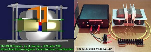
The Motionless Electrokmagnetic Generator, Extracting Energy from a Permanent Magnet with Energy-Replenishing from the Active Vacuum
from Thomas E. Bearden, Ph.D. James C. Hayes, Ph.D. James L. Kenny, Ph.D. Kenneth D. Moore, B.S. Stephen L. Patrick, B.S.
"..This one works beautifully and produces COP=5.0..." has said Tom Bearden
The MEG diagrams published in these pages are currently under test by JL Naudin and may be subject to modifications after that they have been published on this site. They are the result of some attempts of a private and fully independant replication by the author. These diagrams are not the original MEG diagrams being tested by the Bearden's teamwork or some accredited labs.
Disclaimer: The author assumes no liability for any incidental, consequential or other liability from the use of this information. All risks and damages, incidental or otherwise, arising from the use or misuse of the information contained herein are entirely the responsibility of the user. Although careful precaution has been taken in the preparation of this material, I assume no responsibility for omissions or errors in the diagrams or measurement datas published here.
US Patent 6,362,718 : Motionless Electromagnetic Generator See the full MEG patent with diagrams ( 15 pages )
Abstract
An electromagnetic generator without moving parts includes a permanent magnet and a magnetic core including first and second magnetic paths. A first input coil and a first output coil extend around portions of the first magnetic path, while a second input coil and a second output coil extend around portions of the second magnetic path. The input coils are alternatively pulsed to provide induced current pulses in the output coils. Driving electrical current through each of the input coils reduces a level of flux from the permanent magnet within the magnet path around which the input coil extends. In an alternative embodiment of an electromagnetic generator, the magnetic core includes annular spaced-apart plates, with posts and permanent magnets extending in an alternating fashion between the plates. An output coil extends around each of these posts. Input coils extending around portions of the plates are pulsed to cause the induction of current within the output coils.
Inventors: Patrick Stephen L; Bearden Thomas E.; Hayes James C.; Moore Kenneth D.; Kenny James L.
Appl. No.: 656313
Filed: September 6, 2000