http://www.cheniere.org/techpapers/Final%20Secret%2013%20May%201994/index.html
PRACTICAL OVERUNITY ELECTRICAL DEVICES
(C) T.E. Bearden
May 13, 1994
Introduction
Recently, my associates and I have filed a patent application on what we believe will at long last reveal the mechanisms for practical overunity electrical devices. It is my purpose in this paper to provide additional information augmenting my former two papers, (1) "The Final Secret of Free Energy," Feb. 1993, and (2) "Additional Information on the Final Secret of Free Energy," Feb. 1994. In this present paper, with the permission of my colleagues, I release the gist of our work on separation of electrical charge into two coupled components Ø (m), where Ø represents the massless charge of the charged particle or mass, represents the fact that it is coupled or trying to couple to the special mass that makes up charged particles [i.e., the special kind of mass that will couple to the virtual photon flux density that is represented by the symbol Ø], and m represents the inert mass component of the charged mass. Since not all masses will couple with Ø , we indicate the type of mass that will couple with it, as m. Thus a charged mass is composed of (Ø ) ( m), which we consolidate to (Ø) (m).
Charge Is Not Quantized
An interesting immediate result is that the massless charge of a fundamental charged particle is not quantized; it changes as a function of the background potential in which it is embedded. So it is discretized as a function of the background potential (i.e., of the virtual photon flux exchange between it and the surrounding vacuum). Otherwise, e.g., there could be no Ø created on any charged particle q, and hence no E-field, and hence electrons would not move in our present circuits. Since they do move in our circuits, charge is not quantized.

Figure 1. Use of Charge Barrier Device to Achieve Overunity in a Shuttle Circuit

Figure 2. Use of Charge Barrier Device in a Shuttle Circuit With Controlled Feedback, to Achieve a True Negative Resistor.
“The Chung’s Negative Resistance experiment” doc is found at:
http://jnaudin.free.fr/cnr/index.htm

In a July 9, 1998, at the 5th International Conference on Composites Engineering in Las Vegas, Dr. Deborah D. L. Chung, professor of mechanical and aerospace engineering at University at Buffalo (UB), reported that she had observed apparent negative resistance in interfaces between layers of carbon fibers in a composite material. Professor Chung holds the Niagara Mohawk Chair in Materials Research at UB and is internationally recognized for her work in smart materials and carbon composites. The negative resistance was observed in a direction perpendicular to the fiber layers. A paper describing the research was submitted by Chung to a peer-reviewed journal, and a patent application was filed by the University. Document source "On Extracting Electromagnetic Energy from the Vacuum," IC-2000, by Tom Bearden
Now, On May 19th, 2001, I have been able to replicate successfully the Chung's Negative Resistance (CNR). You will find in these pages all informations and datas about the CNR experiment that I have done. The CNR experiment has been conducted so as to be closer to the original Chung's design which is fully described in the paper "Apparent negative electrical resistance in carbon fiber composites," by Shoukai Wang and D.D.L. Chung - Composites, Part B, Vol. 30, 1999, p. 579-590.
• The main CNR experiment : An Apparent Negative Resistance has been measured successfully
• CNR v6.0 tests : A four-lamina carbon fiber composite
• The CNR photos album
• How to build and test yourself the CNR
• How to build and test yourself a four-lamina composite CNR
• A simulated model of the CNR
• The CNR effect can be simply explained by the Ohms Law ?
• A CNR without Carbon Fiber....
• Drift-diffusion balance explains `negative resistance' of material by Nadya Anscombe ( Electronics Times )
• US5059582: Superconductor-metal laminates and method of making ( FULL patent ) by Chung; Deborah
• Industrial Inventions from the DOE Energy Related Inventions Program (ERIP) : Carbon Fiber Metal Matrix Composite Superconductor Sandwich (Chung)
CNR builders reports and tests feedback :
• A successful CNR replication by Roger Burley
3RD DOC
http://jnaudin.free.fr/html/meg.htm
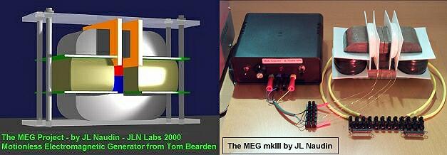
The Motionless Electrokmagnetic Generator, Extracting Energy from a Permanent Magnet with Energy-Replenishing from the Active Vacuum
from Thomas E. Bearden, Ph.D. James C. Hayes, Ph.D. James L. Kenny, Ph.D. Kenneth D. Moore, B.S. Stephen L. Patrick, B.S.
"..This one works beautifully and produces COP=5.0..." has said Tom Bearden
The MEG diagrams published in these pages are currently under test by JL Naudin and may be subject to modifications after that they have been published on this site. They are the result of some attempts of a private and fully independant replication by the author. These diagrams are not the original MEG diagrams being tested by the Bearden's teamwork or some accredited labs.
Disclaimer: The author assumes no liability for any incidental, consequential or other liability from the use of this information. All risks and damages, incidental or otherwise, arising from the use or misuse of the information contained herein are entirely the responsibility of the user. Although careful precaution has been taken in the preparation of this material, I assume no responsibility for omissions or errors in the diagrams or measurement datas published here.
US Patent 6,362,718 : Motionless Electromagnetic Generator See the full MEG patent with diagrams ( 15 pages )
Abstract
An electromagnetic generator without moving parts includes a permanent magnet and a magnetic core including first and second magnetic paths. A first input coil and a first output coil extend around portions of the first magnetic path, while a second input coil and a second output coil extend around portions of the second magnetic path. The input coils are alternatively pulsed to provide induced current pulses in the output coils. Driving electrical current through each of the input coils reduces a level of flux from the permanent magnet within the magnet path around which the input coil extends. In an alternative embodiment of an electromagnetic generator, the magnetic core includes annular spaced-apart plates, with posts and permanent magnets extending in an alternating fashion between the plates. An output coil extends around each of these posts. Input coils extending around portions of the plates are pulsed to cause the induction of current within the output coils.
Inventors: Patrick Stephen L; Bearden Thomas E.; Hayes James C.; Moore Kenneth D.; Kenny James L.
Appl. No.: 656313
Filed: September 6, 2000