--"Some of the above can get complicated… if you have any questions, you are welcome to freepmail me." I have been around pitot tubes a bit and have one or two around of different lengths. And a few used Magnehelics from my now unused ductwork.
That said, my system is a DUCTLESS type mini split heat pump.
Return is in the top. 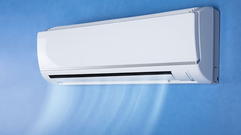 NOTE: This is something I do for fun, I have an HVAC son in law but he is always working and a graduate engineer daughter with three of my grandkids and a full-time job. Even when I'm at my daughter's house she is always thinking about the kids; no time for my projects!!!
To determine the COP I need the S&R temperatures, Airflow rate, and power consumption. Not certain but think that is what is needed. Works well for wet systems GPM x Delta T x 500 yields the total Btu.
The HP uses both an outdoor reset and guessing a PID controller to modulate the pump and blowers so the output just equals the load; very efficient and constantly changing.
I feel like a blind guy describing an elephant, I do not actually know how it works.
--"That way in the future, you can just use the pressure drop as a proxy for the flow. "
Using an anemometer on both supply and return, it is not a nice smooth column of air. Yes, an average across the opening can be determined but guessing it is not linear as the flow changes.
Also guessing that the blowers are DC and a current transformer will not work to measure the current draw.
I have seen procedures to determine the COP using the supplementary electric resistance heat in the unit as a known load and the delta T... I installed the HP mostly for cooling, so no E-R elements.
Thank you for thinking about my system.
Before I retired I was in a large lab full of pilot plants for testing new processes; million dollar tinker toys. After verifying the process... they are scrapped! I'm certain that I could have found what is needed in the scrap bin and I was surrounded by sharp engineers that would point to what would work.
“Works well for wet systems GPM x Delta T x 500 yields the total Btu.” I believe that the relationship you are looking for with air sensible heat is BTU/hr = CFM x ΔT x 1.08. For the record, this relationship assumes 0.075 lb/ft3 air density which should be fairly close to what you have since your air temperature will be close enough to 70 degrees F on the return side and elevation is not that big a deal in Northern Illinois. Converting into Watts so that you can calculate your COP, one Btu/hr is equivalent to 0.293 Watts. Then all you need to calculate is your input electrical power in Watts.
Re your comment “Using an anemometer on both supply and return, it is not a nice smooth column of air.” That will be true but if I wanted to measure airflow on a unit like what you have in the picture, what I would do is duct tape some fairly stiff cardboard on the return air side (which will be more even than the supply side) and essentially create a rectangular duct for it. To make sure the entrance loss is minimized, I would flare out the opening at the top with a 45 degree angle on it. Some dividers in the top part of the duct would also help to straighten the flow out. Then just about say 6” above where it connects to your unit, I would put some holes just big enough for a Pitot tube (or holes big enough for your anemometer) and do a traverse with that. My guess is that with a short 2 or 3 foot long cardboard duct, you will be able to establish a reasonable flow rate and the cardboard duct won’t add any significant resistance that would change the flow rate from what it would be without it.
“….but guessing it is not linear as the flow changes.” If it is changing that rapidly, then some condition will need to be created that holds it steady for the time needed to run a test. I can’t imagine it is changing so rapidly that this can’t be done. Once a traverse is done, find a spot that represents as close to the average as possible and leave the anemometer or Pitot tube at that location and see how it varies over time. If using a Pitot tube that is located at a good ‘average location’, the velocity pressure it provides can be used to log data that can give you a trend of what the flow rate is. I’m still thinking that taking a pressure differential and calibrating that to your flow measurement would be the best way to log the flow. To do that, just create a piezometer ring on the three sides of your temporary ductwork on the return air side (at the plane used for the traverse) and take the differential between that ring and the room. Obviously a different method will be needed in the long term.... this is ok for a ‘test’ but no one will want a ‘cardboard duct’ hanging in their space for any length of time.
“Also guessing that the blowers are DC and a current transformer will not work to measure the current draw.” But to calculate the COP, don’t you want the input electrical power to the whole unit… not just the blower? Maybe calculating COP is a bit different than what I thought….