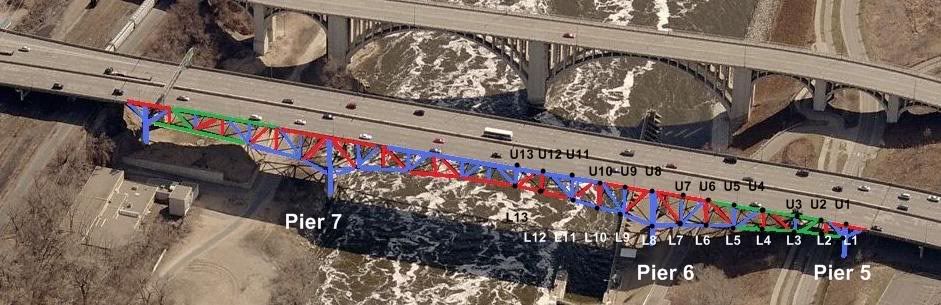
Check out my diagram below--do I have the labeling right? Now it's a lot easier to talk and see at the same time.
Now, let's establish how the bridge stands up.
* Cantilever bridges are built out from the piers. Chords on top are tension, chords on bottom are compression.
* Truss bridges are built from pier to pier, tension on the bottom, compression on top.
* A Cantilever bridge with a suspended truss span has cantilever arms reaching out from the piers, then a truss span hanging from the ends of each cantilever span.
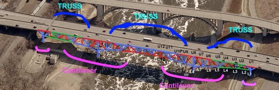
So, the tension/compression diagrams in the MnDOT doc show that this is a cantilever bridge with a suspended truss span. There's a bit of overlap between the two span types, as can be seen in this labeled diagram. The Cantilever extends out from Pier 6 from U12 to U6, with the compression chords from U12 to U10 and U6 to U4 acting as tension chords. Similarly, the Truss Span extends from L9 to the L9 on the other side of the river (same spot, other side), with the L9 to L11 compression chord also working as a tension (the entire span, except that last 40' segment from L8 to L9 at each end). (Of course, if my whole diagram is backwards, it makes perfect sense, with U6 to U2 and L5 to L1 as "reversal members" -- able to function both ways).
Now, look at where Jeffers determined the failure occurred. U10/L10. It's right at the outer extremity of tension members on the top chord. And, in the video, it looks like the failure at the north end also occurred right at U10/L10.
Now, imagine (hypothetically) the center span standing without the side spans. It now has to function as a truss span, compression across the top, tension on the bottom. What will fail? The compression members on the bottom will probably function pretty well as tension members, they're big and beefy. But the tension members will buckle under compression.
So, I'm thinking, the south arm may have fallen first. Jeffers is exactly right on how the main span fell, but I think the south span triggered the main span. (Mainly because it fell so crooked while the rest of the structure fell straight. With a long, complex set of spans like this, span like this, you'd expect a point failure somewhere to take out one span in an asymetrical way, then the other spans to fall like dominos as they lose their counterbalancing cantilever arms, and the girder spans on each end to be yanked off their piers or shoved off their piers as the main spans go).
So, Jeffers is right on the main span, and this is why.
The south cantilever platform, from U12 to U4, can stand on its own only if its balanced. If, say, the south half (landside) was to collapse, then an unattached north side of the cantilever platform would simply dump itself into the river.
And, the north side, attached to the suspended truss and whole north cantilever platform (over pier 7), wouldn't simply dump itself into the river, it would try to act as a truss span, from pier 6 to pier 7. But, this isn't going to work. It's not designed to hold up that way--it would need a truss network with a continuous compression member across the top. Which it doesn't have--it's tension from U10 to U8. The truss system is fine, actually, from L9 to L9 across the river. But not from L8/U8 to L8/U8.
So it will fail.
Where will it fail?
The tension chord from U10 to U8 will buckle. Crunch. Game over. Which is exactly what you've shown, Jeffers, and the video clip shows happening on the other side of the river.
So, it could have been an initial failure on U10, south side. But, you'd think that would have resulted in the main span twisting much more as it dropped. As it is, it fell pretty flat. It seemed to take a few seconds for things to fail. Maybe those tension members handled the compression for about 5 seconds as they slowly got bent out of shape and twisted apart. That's how long it took the same failure to occur in the north landside arm.
So, seems to me, it's much more likely that the initial failure was indeed in the south landside span. Between Pier 6 and Pier 5. Something happened on one side or the other, the west side?? since the deck seems to have flopped to the east. Then the east truss/cantilever arm held for the same 5 seconds, and failed. That makes for the twisted deck. And something in there should also account for the rotating king posts. If the west side, south arm failed (around, say, U6 or U4), then the king post would still be intact. Not sure on the rotational movement, but there's probably a few good reasons.
This brings the initial failure back to a small member somewhere, rather than a massive failure of a main structural member, with a result in s similar failure on the other truss arm, which seems more plausible overall to me.
Hope this makes some sense, I'm staying up *way* too late...
Kwuntongchai