In a silly mistake that I've paid for many times over the years, I sold my "Handbook for Civil Engineers" during tight times in my younger days. "Vector Mechanics for Engineers; Dynamics" and "Applied Physics" are no help, they don't address any but simple trusses.
"Vector Mechanics for Engineers; Statics and Dynamics" moves beyond simple trusses, but finding the exact case under examination here is problematic too.
Having exhausted local resources, I went to a website maintained by Johns Hopkins University which allows you to design a truss and calculate the forces on each member, here:
http://www.jhu.edu/~virtlab/bridge/truss.htm
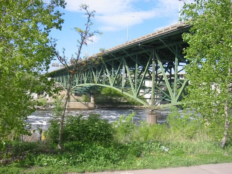
To refresh everyone's memory, here's a picture of the bridge before collapse:

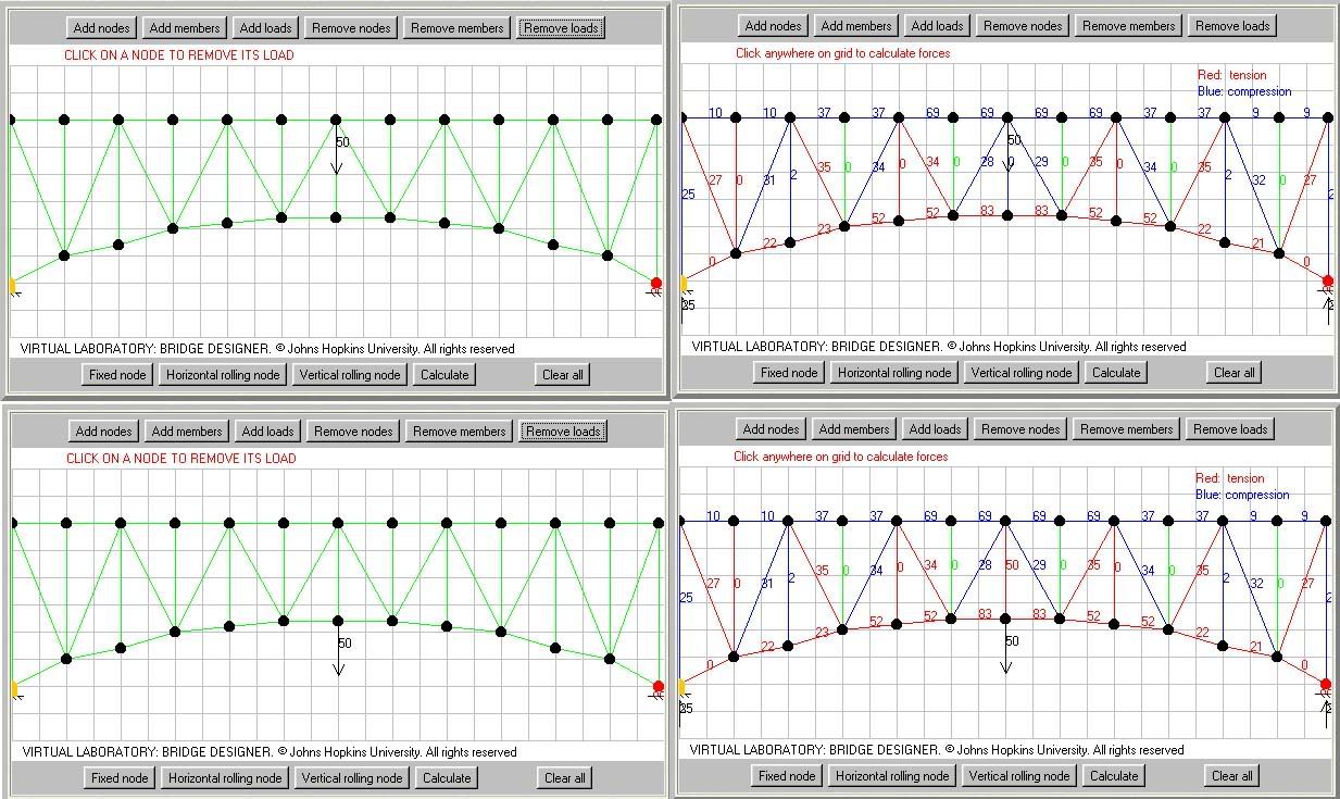
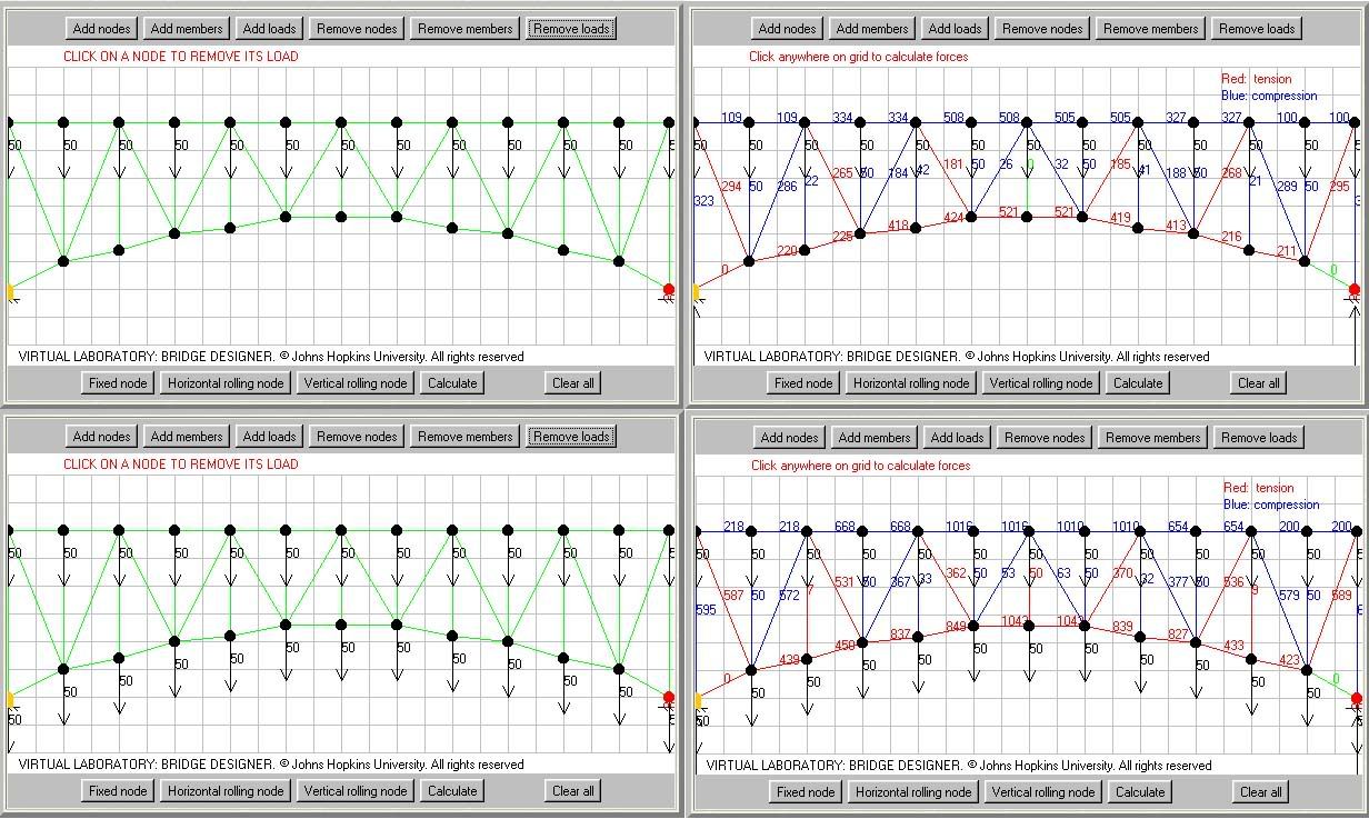
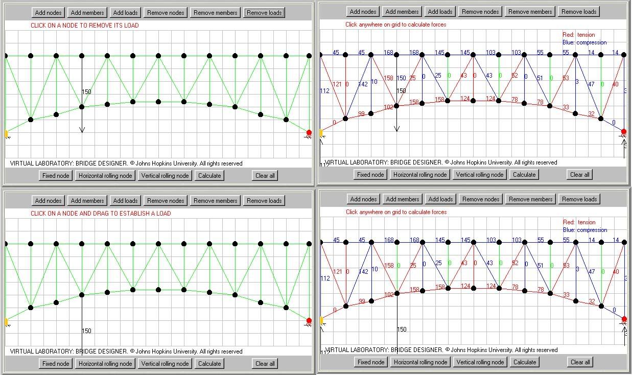
The images below show a truss very similar in design of the mainspan of the bridge that failed. Notable differences may be heigth to depth to span ratios of the truss, which will affect the magnitudes of some of the forces in play, but not the types of forces in play, namely tension and compression. The number of panels and the placement of diagonal members precisely matches the prototype truss used on the collapsed bridge.
In the first image, I used the simple case of a point load, applied first to the top chord of the truss, centerspan, then to the bottom chord of the truss, centerspan. On the left, you see the load and where it is applied, on the right you see the resultant forces on each member after calculation.

In the second image, I applied uniform loading across the span of the bridge, first to the topchord, then to both the top and bottom chords. Again, the left panels show the loads, the right panels show force resolution.

In the third image, I applied assymetrical loading, first to the top chord, then to the bottom chord, loads at left, resolved forces at right.

My conclusions are as follows:
1. Spunkets is largely correct in saying that most members of the bottom chord of this type arched truss are usually in tension.
2. Supercat and I are correct saying that the bottom chord members closest to the support piers are either not in tension, are in tension with zero magnitude, or are in compression under some loading conditions.
3. Under none of the tested load conditions were those bottom chord members adjacent to the piers in tension with greater than zero magnitude.
4. Under centerspan point loads, tensile stresses were maximized in top and bottom chord members nearest to center span. Tensile and compressive stresses in diagonal members tended towards maximum at or about the quarterpoints of the span. Tensile stresses in vertical members trended towards maximum at the span quarterpoints in the case of top chord loading, and at misdspan, and, to a lesser extent, the quarterspan points in the case of bottom chord centerspan point loading. Kingposts on the piers carried significant, but not maximum loads.
5. In the case of uniform top chord loading and uniform top and bottom chord loading, tensile stress in the bottom chord and compression stress in the top chord trended towards maximum at center span. Tension and conmpression stresses in diagonal members trended toward maximum nearest the piers. Vertical members under uniform top loading conditions were in compression, with magnitudes equaling the imposed load in the case of struts between downsloping diagonals, and with part of the compressive stress distributed to the diagonals in the case of verticals located at the apex of two adjacent diagonals. Kingposts on the piers carried significant, but not maximum loads.
6. In the case of nonuniform assymetrical loading, top chord compressive and bottom chord tensile forces reached maxima between the imposed load and midspan. Compressive and tension stresses in diagonals reached maxima between the point load and the pier supports, with a secondary maxima at the mirror image point in the span with respect to center. Forces on vertical members were negligible in comparison with the exception of the vertical member actually loaded in the case of top loading and the kingposts. Kingposts on the piers carried significant, but not maximum loads.
7. Maximum stresses per member were tensile, applied to bottom chord memnbers, in the case of symmetric point loads, and uniform top chord loading. Maximum stresses per member were compressive, and applied to top chord members, in the case of top and bottom uniform loading, and in the cases of top and bottom assymetrical loading.
8. Failure of the river side bottom chord member closest to the southeast pier probably was not the initial trigger in the collapse sequence, as it appears to be lightly or not loaded at all under any of the tested loading schemas. Theoretical analysis of the failure sequence is contra-indicated, because we do not know how the structure was loaded at the time of collapse, nor do we know the design stresses on any of the members, either at construction, or after aging, corrosion and weathering. Further, loading considerations at the time of the collapse were dynamic in nature, not static as was used in the above calculations, which opens several cans of worms, including the possibility of resonant vibration effects. Instead we are left with empirical analysis of the collpase, i.e. that which remains, in imagery, video, and in steel and concrete reality. Without access to the bridge debris, we are probably correct in localizing the collapse initiation to the southeast corner of the bridge. We are probably correct in saying that the southeast kingpost buckled before any of the other three. However, attempting to resolve the trigger event further without access to the bridge debris is probably impossible. The failure of any component in the eastern truss assemblies, southern sidespans or mainspan, could have triggered the collapse. With the information currently in hand, we've taken this about as far as we can go. Final conclusions my have to wait for the official reports, which may or may not be conclusive, and which may or may not be controversial. Neither the FEMA nor the NIST reports of the WTC 1 collapse utilized the available oxygen budget for the fires, and neither went very deep into the culpability of the hat truss assmebly's load re-distribution in triggering the progressive collapse. Sometimes even the experts, with access to all the available data, don't report the whole story. As unsatisfying as that can be, that's just the way it is. In this case, we have a good chance of getting answers, but we will have to wait for them. When the final reports come out, I imagine we'll all be back here to go through some of this again.