In this case however, it's not a simple truss. It's an arched truss, and in my opinion, has a strong cantilever element to it as well. Here's a picture of the bridge, looking northeast, before the collapse:
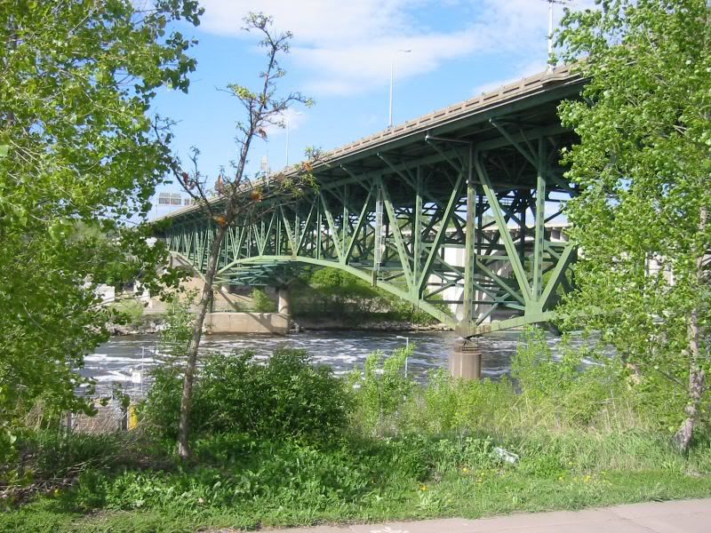
A simple truss has flat bottom and top chords, as indicated in your excellent diagram.
An arched truss incorporates the strength of an arch into the truss framework, usually as the top or bottom chord, sometimes in between the two.
All of the above can function as standalone units between piers.
The cantilever design comes into play when superstructure components on the shoreward side of the mainspan piers counterbalance all or part of the weight of the center span superstructure. If one span of a cantilever fails, the adjacent spans usually fail in sympathy, because the counterbalancing weight has been removed.
I agree that this bridge is not a true cantilever. There are no massive counterweights attached to the approach ends of the superstructure, there are no free ends in the center of the mainspan, and no pivot pin to join two cantilevers together.
However, it's not a simple truss either. There's an arch to contend with, and it is very clear, on two counts, that the spans are not independant.
Obviously, the northern approach span failed after the center span dropped. It failed just as you would expect half a cantilever to fail, by rocking shoreward in the absence of its counterweight. Just as obviously, the approach spans were not designed to be independent, as the superstructure ran over the piers on into the approaches without interuption at the piers as is normally seen in simple post and beam, post and plate, or post and truss design.
Without the engineering drawings, and a lot of processing time, I can't say to what degree arch type, truss type, and cantilever type load distribution mechanisms were in play in the static design, much less in the dynamic forces of daily use, and further still from the dynamics of failure.
The best I have to go on here are the images, statements from MnDOT to the effect that the bridge was designed such that failure of any major component would fail the entire superstructure, and the specifics of the failure sequence itself.
At this point, rather than labelling the design a truss, or cantilever, or arched truss, about the best I can do is call it a unitary design, somewhat like modern automobile frames are put together, putting several different load distribiuting mechanisms into play to create one overall structure. In fact, I can't even say whether the bottom chord was in tension or in compression. That arch is a pretty flat one, as arches go, but arches are in compression, as are the bottom chords of cantilevers. As you note, the bottom chords of trusses are in tension, and its beyond my abilities to say whether this design was more of a truss, arch, or cantilever.
It's hard to tell in the photos, but my impressions are that in your first photo, the failure of the bottom chord, as far as visibility allows are at least consistent with a compression failure, i.e., diagonal shear. That's not good enough to be conclusive, and I'm not engineer enough to analyze this design just from the pictures.
On the good side, from the article posted above, MnDOT is looking at the same general area we are, southeast side of the bridge. Between us and MnDOT we have one or more layers of usually clueless reporters, but we're in the same ballpark no matter how you look at it.