"3. Under none of the tested load conditions were those bottom chord members adjacent to the piers in tension with greater than zero magnitude." That must be the case in the bridge you have, because you've designed it that way. Your model doesn't represent the same bridge. You have a bearing under the first king post with nothing on the other side, so no forces will ever appear in that beam. You could take it right out and the situation wouldn't change.
Look at the pic of the real bridge. It has another section on the other side of the first king post, so you must ignore that first triangle and only look at the forces that appear at other king post connections. Then you can see that the bar that broke was part of a complete king post truss element, whose base is always in tension.
In a real bridge, the only way to get the lower chord in compression is to remove the bearing and fix the position of the chord ends. The real bridge has a bearing. It could freeze, but that's unlikely here, because it would be obvious to the inspectors that it was approaching such a condition and the fix is simple cleaning. there appears to be rust, but good maintenance and paint. Also, that chord element in the real bridge appears to be torn free, not buckled, or shoved back. The symmetric chord element on the other side of the post did not break. That's why that section torqued over after the other side went straight down. Note that the SW side assy just slid off the post.
In the figs I drew everything has simple supports at the bottom. That's the same as a bearing. I also just gave a simple triangle to show how the forces look in that. The king post complicates things, and so does showing forces in assemblies of more than one element. So I took it out and didn't address anything except the simple triangle and what's above the post on the real bridge. Time...
Thanks for the link. http://www.jhu.edu/~virtlab/bridge/truss.htm . I won't have time to look at it yet. I'll just makes some comments. A real bridge must be more, or less simply supported to allow for expansion/contraction, and has bending moments in both the structure and it's elements. The model uses fixed ends somewhere to show forces.
MAybe you could make the 3rd, or 4th node look like the junction of the 2 bridge halves at the post. What does green mean in the figs? Does the model allow elements to be removed? The chord element I circled in the other post is critical and broke. Take it out and the bridge falls. The above doesn't show that for the reasons I gave. If the model can be changed, it would be possible to see the tension rise in that chord section when adjacent beams are removed.
You have a bearing under the first king post with nothing on the other side, so no forces will ever appear in that beam. You could take it right out and the situation wouldn't change. You are correct in noting that the model does not match the bridge. However... In a real bridge, the only way to get the lower chord in compression is to remove the bearing and fix the position of the chord ends.
That is just plain wrong. In the real bridge design, that chord will always be under substantial compression (unless something else on the bridge has already failed catastrophically). Imagine that the king post over one of the piers were split in two along its length, with one half attached to each half of the bridge. What would happen? The side of the bridge away from the other pier would want to fall away from it. To prevent that from happening, the top of the bridge there must be under tension. To balance that, the bottom must be under compression.
Cantilevered truss arrangements are frequently used in building bridges because they substantially reduce the tension and compression loads found in the center of a span. Since the top center of the span is under compression, any tensile force applied to the top outside of the bridge will reduce the tension by an amount equal to such tensile force.
spunkets wrote:
"...Look at the pic of the real bridge. It has another section on the other side of the first king post, so you must ignore that first triangle and only look at the forces that appear at other king post connections. Then you can see that the bar that broke was part of a complete king post truss element, whose base is always in tension.
In a real bridge, the only way to get the lower chord in compression is to remove the bearing and fix the position of the chord ends. The real bridge has a bearing."
******************
I understand your point, and it is a valid question. You note I only used "half a triangle" above the piers, and this was by concious choice.
It does not affect the force resolution solution however, at least, not in your favor.
I used that configuration because of limitations in the model, sizewise, so that I could include all panels in the prototype main span truss.
A simplified (fewer panels) diagram with full panels above and on both side of the piers as you suggest, puts the bottom chord in compression at those points under uniform top and bottom chord loading, and resolves the forces at zero magnitude under uniform topchord only loading schemas.
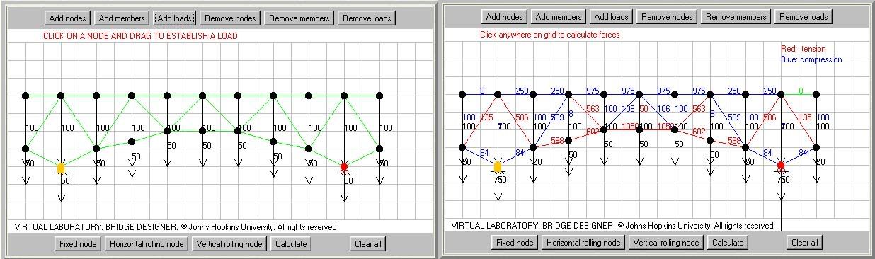
Note also that in the above and all previously posted stress resolution diagrams, the left truss support represents a fixed bearing surface, while the right truss support represents and is modeled after a roller bearing. This is a limitation of the modeling software and is mandatory prior to executing the force resolution calculations.
For further consideration, here is MnDOT's own stress diagram, from page 50 of the 2006 inspection report, an excellent source posted by B-Cause, in post 2631:
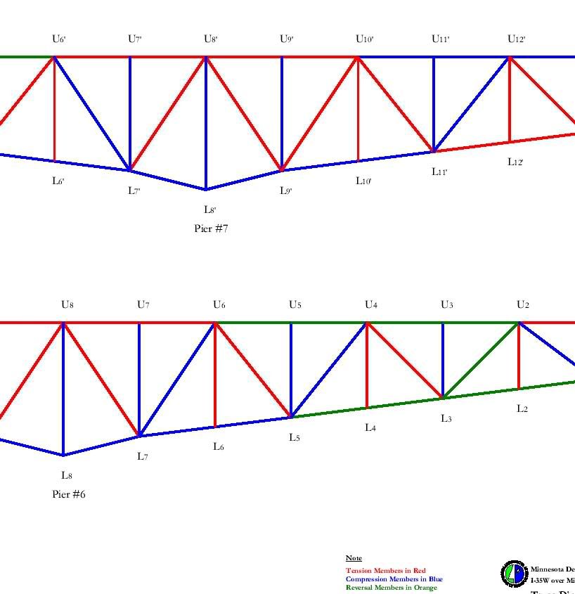
Please forgive the image format and quality, I had to lift if from a PDF document and rotate it 90 degrees to make the salient points visible and legible.
Note that MnDOT shows the bottom chord in compression for the first three panels on either side of the piers.
Further note that the topchord is in tension over two of those three panels either side of the piers, and the combination of these two stress resolutions represents the cantilever element of the truss design I spoke of since early in this thread. This cantilever element is discussed at some length in the official MnDOT report, and probably was instrumental in the collapse initiation of the north sidespan after the mainspan collapse sequence was complete.
I fully agree with your observation that the bottom chord failed just north of the southeast pier. I am not willing to say with certainty that this failure was the trigger for the collapse sequence, but I'm also not willing to say it wasn't the initiating event either. It is a critical component, and its failure would not go...unnoticed...but it does appear to be lightly loaded under normal equilibrium bridge loading conditions.
I will also repeat my earlier observation that the failure of that bottom chord member appeared in the imagery to be consistent with compression failure, i.e. diagonal shearing.
With the information available, this is as far as I am able to go.
The full MnDOT inspection document can be found here, again thanks to B-Cause:
http://www.dot.state.mn.us/i35wbridge/pdfs/06fracture-critical-bridge-inspection_june-2006.pdf