
The second photo in 1811, the photo showing the collapsed wall, was taken later when there was greater damage. It was taken at about the same time as this photo:

h/t maggief for this photo.
Posted on 02/12/2017 4:26:47 PM PST by janetjanet998
Edited on 02/12/2017 9:33:58 PM PST by Admin Moderator. [history]
The second photo in 1811, the photo showing the collapsed wall, was taken later when there was greater damage. It was taken at about the same time as this photo:
h/t maggief for this photo.
OK, thanks.
I do not remember them stopping the flow twice in the events timeline,
but is obvious that they did and I either missed it or forgot.
What a mess!
First of all, a new engineering team versed in correcting dam issues has to be brought it with some reliance on a forensic team looking at the original issues and investigating what happened.
After the new team comes up with some A, B, C approaches that same forensic team needs to do an internal Peer Review for the new team to avoid not having looked enough at choices.
The spillway gates are performing well it appears and duplication them adds six months of work to an already too tight schedule. Add another spillway later in a manner that does not involve the main dam if you must, but put this thing properly back in service with features revised to avoid failures.
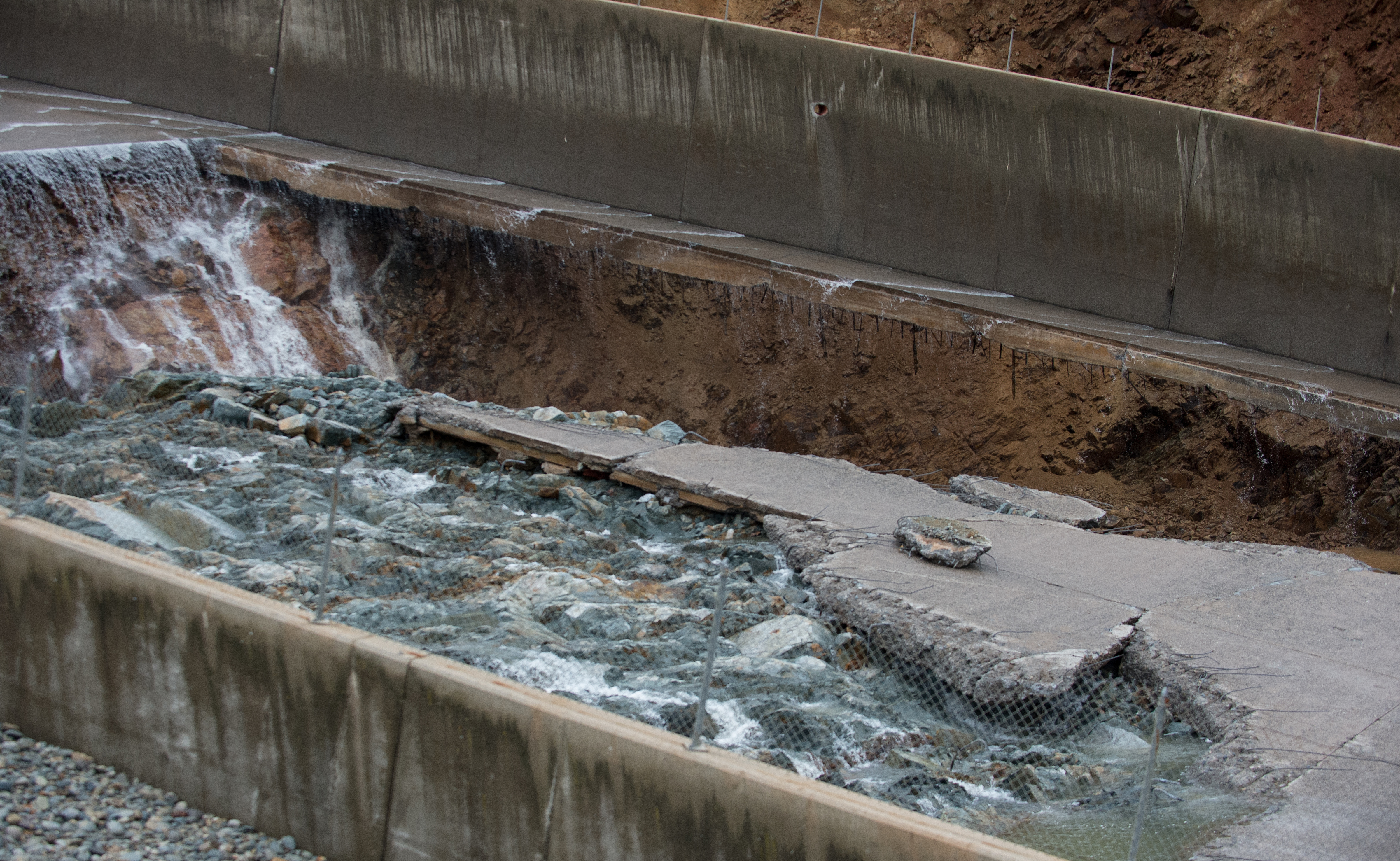
In your first set of photos there is indication of a brownish mud slab perhaps placed with lean mix and local aggregate. I think they place fill where they had no solid rock, placed a mud slab to get up to sub-grade and then placed the main slab on rock or mud slab.
Confirms my point of variable bearing and some narrow space issues possible with hydrostatic pressure between solid rock and concrete slab.
Now, this is arm chair quarter back stuff and the original designer and the forensic firm are going to issue a real report worthwhile and all our speculation is just that — speculation on a public event.
I don’t know why the image is being blocked.
Here is a link
http://www.insidecdcr.ca.gov/wp-content/uploads/2017/02/KG_oro_spillway_damage_10060.jpg
The zoom feature on that photo is incredible.
Somewhere up the thread, someone said there was no rebar in the concrete.
There obviously was.
Hi Ray76, KC Burke, Mariner, Repeal The 17th,…..I'm a bit behind in questions asked.
Other Engineering Forums have been covering/discussing these same good questions, plus some new interesting points.
>>Q: "Given the amount of erosion what are your thoughts regarding the feasibility of the spillway remaining at this location?"
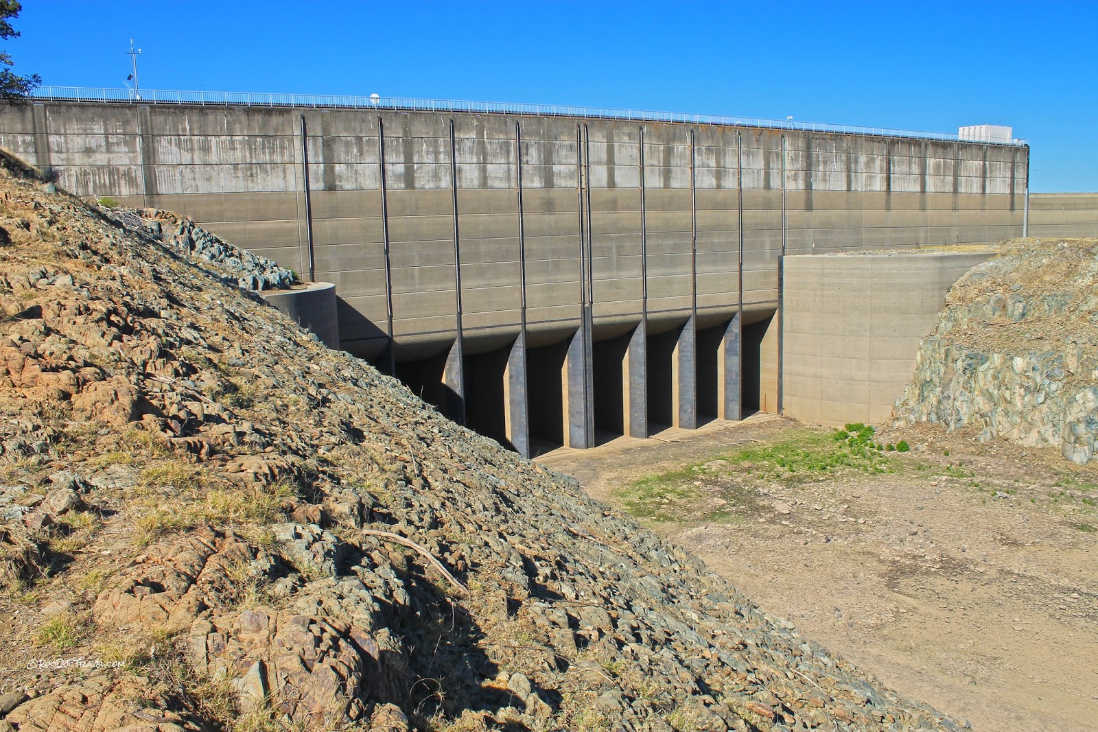
..I would say the first obstacle to this is the Main Gate orientation regarding laminar flow. The whole design of the chute & Main Gate Structure is straight. It is aligned to a massive concrete structure (that still operates fine) that contains meticulously designed shapes to prevent vortices, turbulence, under all flow rate specifications. This concrete structure is also anchored into bedrock. At the very bottom of the spillway, the rock has shown itself to be time proven & solid. If a choice ($costly$) were made to move the spillway you lose two immediate solid gold starting & ending points.
There are modern technologies that could provide deeper core anchoring to overcome any new "cut line" from the severe erosions/damage.

>>Q/discussion: "It also appears there were slab areas where competent rock was not available to provide the grade needed for slab placement."
"This means that water that got under the slab under pressure would have wedged under that portion placed on rock and lifted it."
=== For slab under pressure water: see: VI-1. Stagnation Pressure Failure of Spillway Chutes
http://www.usbr.gov/ssle/damsafety/risk/BestPractices/Chapters/VI-1-20150610.pdf
Quote: "Stagnation pressure refers to two conditions that can result in damage and/or failure of the spillway: (1) High velocity, high pressure flows enter cracks or open joints in the spillway flow surface (such as a chute), which results in uplift pressure that lifts (displaces) portions of the spillway conveyance feature; and (2) High velocity, high pressure flows enter the foundation through cracks or open joints in the spillway flow surface, which results in internal erosion of the foundation and loss of support of portions of the spillway conveyance feature [26]."
===
..Yes to water under the slab. But to which effect was key? (1)(2)? The best information, to what was developing as a pre-failure to the blowout, would be from human intelligence information on the recurring repairs. There should have been sign of "uplift" cracking or "loss of support" cracking. Images show that drains in the area of the failure were not draining equally (or zero) compared to the neighboring sections. So to what degree each element was in play gets back to any fore knowledge by the construction workers & inspectors on what they were observing in the surface fracturing via repairs.
(discussion..more re: in lifting the slab (not enough hydraulic pressure?) - Keep in mind the 15 inch thick slabs were heavily anchored with steel (rebar) into the bedrock. The tremendous weight of the waterflow has a much higher weight compression force than a small waterflow under the slab(s).
However, photographs of the early construction show a "compressed" gravel layer prepared for the concrete slab pour. This gravel is also described as a medium to capture any water for the under-slab drain piping. So you have a ready made layer for scouring erosion, besides any deeper fractured rock anomaly.
Regarding "competent rock": Yes, they found areas that had to be restored to grade level using concrete (see image above- construction blueprint). The prints denote "Details are typical for case where 'accept. rock' is below cut grade". What is not in these prints, but are found in construction commentary archives, is that they encountered seams of "less than acceptable rock".
Archives Construction Report- direct quote: “proved to be of a lower quality rock than anticipated. There were several large seams running parallel with the chute. The planned anchor bars were replaced with grouted rock bolts, pigtail anchors, and chain- link surface covering in that area”
This means that they took extra measures to shore up these areas they thought were not as complete as good bedrock.
KEY Point: There may be a human error element to stress fracturing in the concrete slabs…
The Oroville dam "operating rules" are very specific on water release rates of change. In Engineering it is known issue where differential expansion rates cause stress fracturing/cracking in anchored concrete.
== reference:
Quote: "Severe problems develop in massive structures where heat cannot be dissipated. Thermal contraction on the concrete’s surface without a corresponding change in its interior temperature will cause a thermal differential and potentially lead to cracking. Temperature changes that result in shortening will crack concrete members that are held in place or restrained by another part of the structure, internal reinforcement or by the ground. For example, a long restrained concrete section is allowed to drop in temperature. As the temperature drops, the concrete tends to shorten, but cannot as it is restrained along its base length. This causes the concrete to be stressed, and eventually crack." http://www.engr.psu.edu/ce/courses/ce584/concrete/library/cracking/thermalexpansioncontraction/thermalexpcontr.htm === Human error (if rules not followed):
Oroville Operating rules quote (re:''Limitation on releases") "C. Releases from Oroville dam are not to be increased more than 10,000 c.f.s nor decreased more than 5,000 c.f.s in any 2-hour period."
http://www.water.ca.gov/orovillerelicensing/docs/FEIR_080722/AppendixA/Extracted_Comments/C0005_SutterCty_YubaCity_Levee%20Dst1_Appendices_Pages_10-177.pdf
=== These rules mean that going from 50,000cfs to 100,000cfs should not occur faster than 10 hours -even rate. And, going from 100,000 to zero should not occur faster than 40 hours.
I don't have any data on past history of rate operation - just that these thermal effects on an anchored concrete slab spillway is a real effect on structural damage (cracking of concrete).

>>Q/discussion: Layers of concrete, Dowel transfer support, Stepped seams, heavy rebar & metal mesh, mud/soil underneath.
Images show that there was heavy rebar used to anchor the 15 inch concrete slabs to bedrock. AS noted above, there were areas that additional anchoring means were employed in areas where they found lesser quality rock, including additional chain link surface covering.
Re: soil or mud: There is no evidence in any of the construction archives where the main spillway where soils existed underneath the slabs. The construction blueprint shows that excavation was done to insure that all surface areas were excavated down to rock.

Large steel dowels were used as load transfer to the main spillway slabs at the edges of the sidewall gates. Other Images (if you zoom) show rows of holes where the dowels were present - before the damage & concrete pulled them out.
The impression of sub-layers in the concrete: The slab horizontal seams used multiple staggered steps to overlap the adjacent slab (see image). Dowel pin holes have not been observed in these "stepped" slab edge images. The sub-layer look may have been from the method of pouring/construction to create the "staggered interlocking steps".
This is all of the time I have for now.
I made that comment. These are the first images where I could see it. There only seems to be some to tie the bottom to the side walls and by today’s standards it is too small and not enough. Maybe I an missing it but I still don’t see any tying the floor to itself in a linear fashion.
Thanks to you all and others posting good information.
>>Follow-up to 1830 <<
It is important to note that “flood control” rainfall at Oroville, where the main spillway was used, were infrequent over decades. However, when the main spillway was used at these times, the drains were showing high flows from the drains. A well sealed spillway should show much less.
The dam expert, Scott Cahill, pointed to these drain flow conditions as a key pre-indicator issue. If money was spent in properly maintaining and/or meticulous analysis and refurbishing were done properly, there should be very little drainage flow when the spillway was in operation.
In addition, a “pre-failure location” showed itself where recurring fixes to cracking were done multiple times. They had ample opportunity to address this, including any revelation of what other measures should have been taken when discovering the cause of whatever these pre-failure analysis findings revealed.
there should be a pile of rebar somewhere further down stream.
I think one of the other items about the re-bar questions is that the photographs have a deceptive scale even when clearly in focus. Our eyes do not really take into account that the spillway is almost 300 feet wide. When we get the pictures of the trucks on the slab, it helps but just looking at the slab damage we need to keep in mind it is 15” thick. Our eyes want to see it like a 5” driveway or an 8” roadbed slab. We can’t see the re-bar remnants due to scale.
Thanks bud. It is great that some of the engineering and debunking forums were able to dig up the construction records and plans.
I did a project once where I was able to show the Owner that we still had the job photographs, the as-built records, and all the documentation for a project we had built the bulk of sixty years prior. It helped us negotiate the new project that was integrated into the same three blocks of commercial historic structures.
>>Question....if there was “heavy rebar” in the spillway.....where did it all go....<<
Hi Spokeshave,
Perhaps my wording would have been clearer in specifying better when I used the term “Heavy Rebar”. I was intending to point out the “large diameter size of the anchoring rebar”. Due to the perspective of scale of the huge spillway dimensions (in images), a viewer may not realize how large the rebar is in size - thus the reasoning for emphasizing “Heavy Rebar”. You will notice in the images that much of this “large diameter” rebar remained anchored in the rock. The hydraulic water turbulence tearing forces broke away the concrete from these large diameter rebar anchors.
Note: you need to zoom to see all of the remaining “anchoring” rebar in the bedrock. This is a testament to how well it was secured into the bedrock - including rock that had a weathered oxidation coloring (typical of “weathered and/or fractured rock”).
Also, in the images, you can see many “string like” wires coming from the concrete blocks. This are the remains of the large size metal mesh that was integrated into the concrete pours.
When the dredging starts, I’m sure there will be images (zoom) that will be enlightening. I believe there will be some of the large diameter “anchor rebar” downstream - as these would have been “pulled out” with the concrete slab pieces.
Thanks. Regarding one of the images at the link.
One minor point to the plaque photo stating “Spillway Capacity 650,000 cfs”.
If they want to completely destroy both spillways (and the dam), they cannot even come near this 650,000 cfs number. The Emergency Spillway was a disaster with just a dinky 12,000 cfs in a short period of time. The Main Spillway was originally designed to safely handle about 250,000 cfs, but that was reduced later to a 150,000cfs operational limit.
Disclaimer: Opinions posted on Free Republic are those of the individual posters and do not necessarily represent the opinion of Free Republic or its management. All materials posted herein are protected by copyright law and the exemption for fair use of copyrighted works.