Skip to comments.
Emergency: California’s Oroville Dam Spillway Near Failure, Evacuations Ordered
Breitbart ^
| Feb 12, 2017
| Joel B. Pollak1
Posted on 02/12/2017 4:26:47 PM PST by janetjanet998
Edited on 02/12/2017 9:33:58 PM PST by Admin Moderator.
[history]
The California Department of Water Resources issued a sudden evacuation order shortly before 5 p.m. Sunday for residents near the Oroville Dam in northern California, warning that the dam’s emergency spillway would fail in the next 60 minutes.
The Oroville Dam is the highest in the nation.
TOPICS: Breaking News; News/Current Events; US: California
KEYWORDS: butte; california; dam; dwr; evacuation; lakeoroville; liveoroville; moonbeamcanyon; moonbeammadness; oroville; orovilledam; orovillelive; runaway; spillway; sutter; water; yuba
Navigation: use the links below to view more comments.
first previous 1-20 ... 2,341-2,360, 2,361-2,380, 2,381-2,400 ... 4,521-4,538 next last
To: mad_as_he$$
I was intending on using the scaffolding angle as a vertical reference for the drain line angle determination. Turns out, the scaffolding is a few degrees off. So I resorted to using two references of workers’ balance in the tilt. They turned out to be more accurate. IN the image you can see a white painted bar line on the wall. That white painted bar line is accurate to vertical. From that, you can see how the scaffolding is tilted slightly to the right in comparison.
To: EarthResearcher333
I got your intentions and understood them. I just had to chuckle at the scaffold tilt, camera angle and the body positioning of the various humans. It has to be very taxing to work at that inclination for hours.
2,362
posted on
03/10/2017 10:21:06 AM PST
by
mad_as_he$$
(Watching Obama tap dance.)
To: abb
Electrical control wiring is the same principle.
The electrical analogy creates visions of a Christmas tree lighting string of pigtail wire nuts (ick). Nowadays transmission line impedance integrity is critical due to the signaling rates & differential lines (RS485, etc). Believe it or not but end to end ground shifting from heavy electrical equipment switching causes more grief as this may cause the working differential voltage (in common mode) to push above or below the receiver's rated clamping limits.
IN one project, in locating the root cause failure, the micro packet protocol on RS485 signaling, would lockup in the microcontroller TX/RX circuits. It was traced back to neutral/ground reference spike shifting between floors in a building when the elevators activated. The big electrical motors caused one floor to shift differently than the other**. Nothing wrong with the control signal wiring. Can't use splicing in the impedance controlled & shielded sensitive stuff. You use impedance matching connectors (usually DB9 or better for RS485).
**Neutral/ground with reference to the central power wiring breaker box array. One solution is to use small signaling isolation transformers - but this requires a constant NRZ/NRZI type of Manchester coding (clock & data combined & PLL extracted).
To: EarthResearcher333
If that wall panel is close to the failure point, the gap could be from the entire spillway shifting downslope slightly, after losing the support of its adjoining panel.
2,364
posted on
03/10/2017 10:38:32 AM PST
by
abb
("News reporting is too important to be left to the journalists." Walter Abbott (1950 -))
To: mad_as_he$$
Did you notice how the camera shot is almost perfectly half way between the spillway slope angle and the true vertical angle? It’s almost as if the brain is compensating for the unnatural illusions (tilt).
“work at that inclination for hours”... I agree. Reminds me of re-roofing 3-tab in the day before nail guns. Had to get curled up to place & hand nail the shingles... and without accidentally hammering fingers.
To: EarthResearcher333
Great pictures and analysis!
Look at the sealant they put on the bottom between the two slabs. It shows how wide the gap had grown. Some of the people in the picture are pointing at it.
It seems nearly inconceivable that the slabs could have pulled that far apart before this started. Even with the slipshod maintenance the spillway was getting in the past, something that large would have been cause for alarm. (At least common sense says it SHOULD have been. So maybe it wasn’t...)
So it seems likely the bottom slab has slid more than an inch downhill. That’s a LOT, and must have done a lot damage we can’t see. No way to fix that, and no way to strengthen it either.
It’s easy to see the whole slab going. They must be aware of that, they just don’t want to talk about it. I’d sure like to see a reporter ask about it in a news conference.
BTW: Your story about the forklift is hilarious. And the same type of flaw can appear in other things as well. Imagine the new hamburger flipper robots becoming unstable... :)
2,366
posted on
03/10/2017 10:47:27 AM PST
by
EternalHope
(Something wicked this way comes. Be ready.)
To: abb
"If that wall panel is close to the failure point, the gap could be from the entire spillway shifting downslope slightly.
I agree. I was searching photo databases to see if there is a tell-tale shift of the slab alignment joint next to this one to get another data point.
To: EarthResearcher333
Thanks ER333 !
That gap filled with grey filler is —very— disconcerting..
2,368
posted on
03/10/2017 11:14:26 AM PST
by
WildHighlander57
((WildHighlander57, returning after lurking since 2000)
To: abb; Grampa Dave; Jim 0216; WildHighlander57; meyer; Repeal The 17th; KC Burke
Rotation of Broken section of Main Spillway placing stress on slab anchor bars..
Hi abb, Looks like it is a rotation movement. The 12" dia drain break behind the spillway wall undoubtably contributed to erosion of the wall anchoring. This wall has substantial mass. I have seen images of load transfer bars holes in sidewall to slab joints. These parallel load transfer bars could bind from a rotational component - rather than "slip" in the normal designed lateral expansion. However, I have not seen load transfer bar evidence on this wall side of the spillway. Only beveled mating joints (you can see this type of beveled joint in this image).
In any case, there seems to be a linking force between the mass of the sidewall and the spillway slab as the force to pull/rotate a slab would be substantial considering the slab anchor bars into rock (they drilled NX holes and then grout sealed the thick rebar anchor bars into the rock).

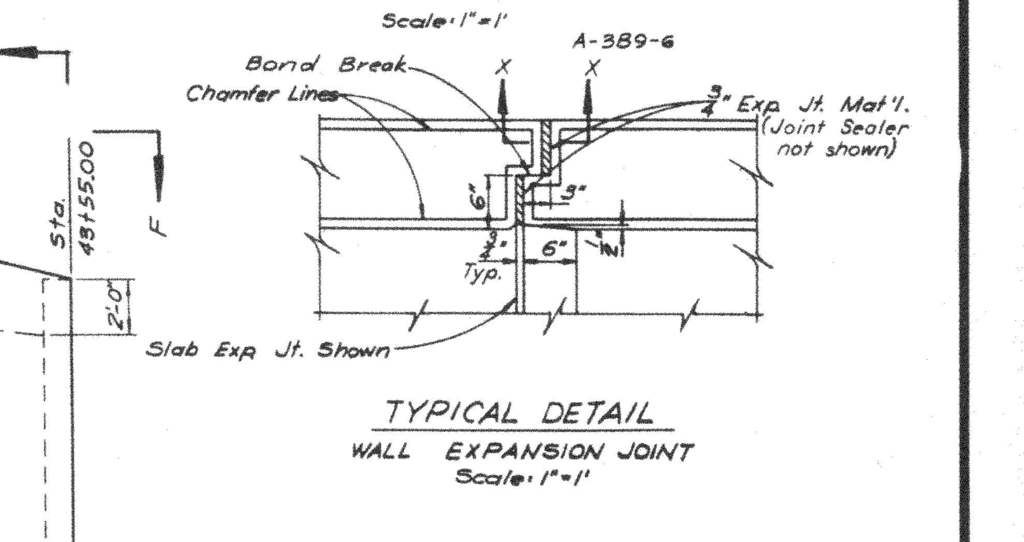
To: EarthResearcher333
Detail of wall expansion joint.

2,370
posted on
03/10/2017 12:39:28 PM PST
by
abb
("News reporting is too important to be left to the journalists." Walter Abbott (1950 -))
To: EarthResearcher333
Thanks, ER333, and others. I’m visiting family so I’m not as attentive to the discussion as I could be.
I wonder if they intend on filling under that left corner or not.
2,371
posted on
03/10/2017 12:40:10 PM PST
by
meyer
(The Constitution says what it says, and it doesn't say what it doesn't say.)
To: meyer
I wonder if they intend on filling under that left corner or not. We can't see how deep it goes under that corner, but based on the shadows it might be a water channel eroded into soft/weathered rock.
It's easy to see how a lot of water could have been flowing under that slab. If they fill the hole in and trap the water I can see how it might even make matters worse. The water is going to get out somewhere.
2,372
posted on
03/10/2017 1:25:22 PM PST
by
EternalHope
(Something wicked this way comes. Be ready.)
To: EternalHope
That’s possible, though I recall seeing some muddy water along that side of the spillway when they had ramped the flow down to about 35,000 cfs or so. A muddy brown/red cold r that had been absent in the days before at a steady 50,000.
2,373
posted on
03/10/2017 1:33:25 PM PST
by
meyer
(The Constitution says what it says, and it doesn't say what it doesn't say.)
To: abb
"Detail of wall expansion joint."
Just to keep in sync: The drawing you reference is a vertical view looking down at the top edge of the sidewall (i.e. showing the Wall Expansion Joint design). You can see in pictures the "Chamfer" beveling at the top of the wall where the metal fencing is located.
Here's the puzzle: In all of the drawings, I haven't seen any "load transfer bars" in the spillway slabs to the sidewall slab joints. Yet, there is forensic evidence it was constructed with load transfer bars - at least in the East Sidewall. All of the slab expansion joints form a bracket or bevel type of "[" orientation from left to right (looking up the spillway). So what is providing the forces between the West Sidewall to the western most spillway slab to get this spillway slab to shift with and rotate with the West sidewall? A true expansion joint is not solid concrete. There may be downstream evidence of West wall "load transfer bars" that could be facilitating this torque & shift.

To: meyer
I think your second-spillway idea is worth consideration even if it takes a couple of years & using the current one in the meantime.
To: EarthResearcher333
West Sidewall Spillway load transfer bar evidence - photo..
Found it. Here is a shot of the lower spillway sidewall. It reveals the holes for the load transfer bars. Creates a new puzzle…. Why did the break in the prior image show a bevel that is opposite of this new image downstream? Was the construction different or altered as they progressed in the lower spillway verses the upper spillway (sidewall junctions)? Need more coffee….

To: EarthResearcher333
Another View showing the West Sidewall joint with the adjacent main spillway slab. This view also reveals an "erosion hole" under the spillway.

To: Bobsvainbabblings
Thanks. His updates are interesting.
To: EarthResearcher333
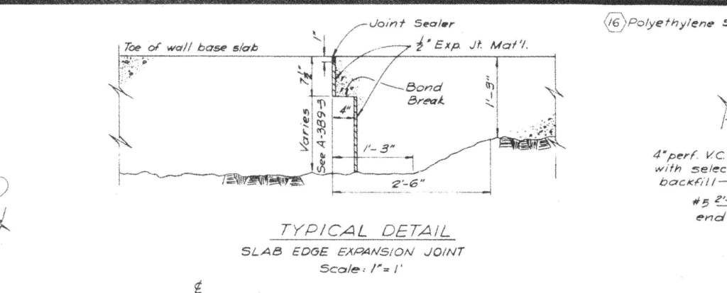
Detail of joint between wall footing and spillway slab.

2,379
posted on
03/10/2017 4:16:01 PM PST
by
abb
("News reporting is too important to be left to the journalists." Walter Abbott (1950 -))
To: EarthResearcher333
Thanks, ER333,
You put so much thought and effort in all of these posts.
I think the arrow in your first picture in #2354
http://www.freerepublic.com/focus/news/3524221/posts?page=2354#2354
does not point to a bell coupling, but simply to a male end,
the bell coupling should point up-slope.
That is the only way I have ever seen VCP laid.
2,380
posted on
03/10/2017 7:21:24 PM PST
by
Repeal The 17th
(I was conceived in liberty, how about you?)
Navigation: use the links below to view more comments.
first previous 1-20 ... 2,341-2,360, 2,361-2,380, 2,381-2,400 ... 4,521-4,538 next last
Disclaimer:
Opinions posted on Free Republic are those of the individual
posters and do not necessarily represent the opinion of Free Republic or its
management. All materials posted herein are protected by copyright law and the
exemption for fair use of copyrighted works.
FreeRepublic.com is powered by software copyright 2000-2008 John Robinson


