Not long after my last post on this subject, I located the failure point, the U10 East Truss gusset, in the post collapse imagery, ran analysis on both post collapse and precollapse imagery of that gusset, and satisfied myself as to the cause and nature of the collapse.
I did not post this additional analysis at that time, for three reasons:
1. The results did not change my original conclusion, that the U10 East Truss gusset fractured as a very early, and probably the prime trigger for the full collapse.
2. The additional analysis was technical in nature, probably not of interest to non-engineers.
3. Other things were going on at the time, demanding my attention.
This post is a shortened version of what I would have posted then, if time had allowed and there had been strong reason to do so.
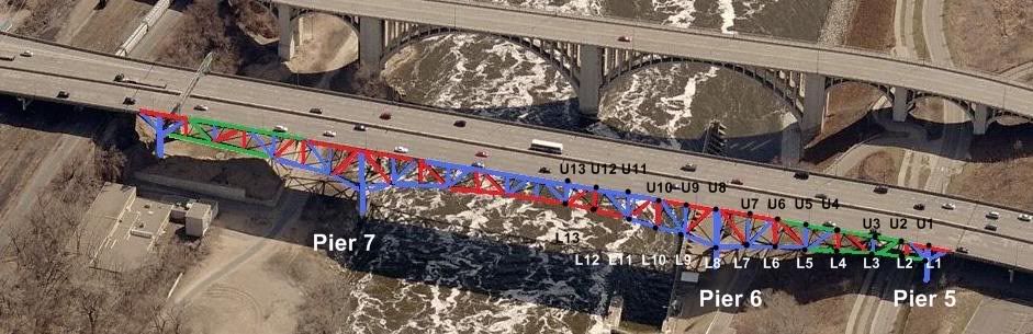
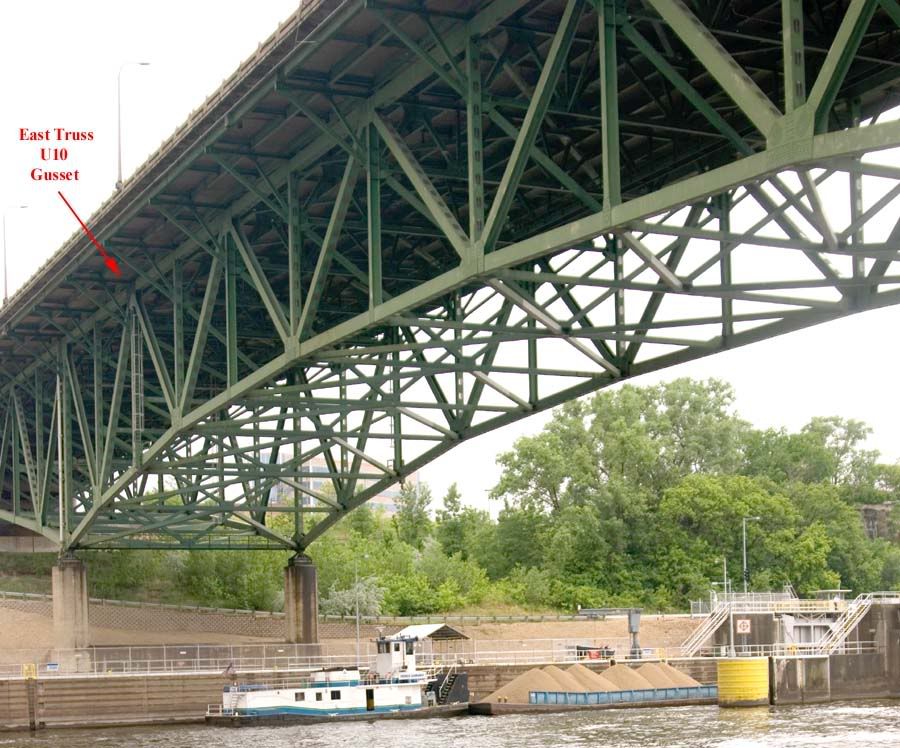
Here is a pre-collapse image of the I-35 bridge, looking southwest, with the U-10 East Truss gusset plainly marked:
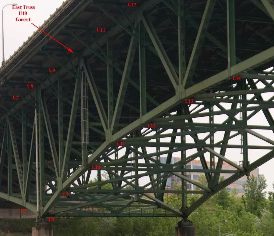
Here is a tighter zoom of the above image, showing discoloration on the U10 East Truss gusset, with other critical points labeled for reference:
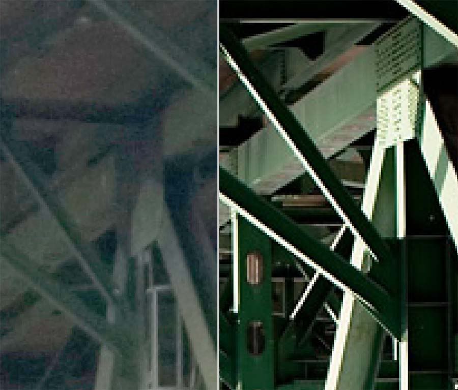
Here is an extreme zoom of the above images, isolating the U10 East Truss gusset, in comparison with a similar gusset which is in better condition and showing more detail:
Given before and after imagery, I decided to reconstruct the U10 East Truss gusset, as seen in the post collapse imagery, for analysis purposes. The following image gives an idea of the method I used to determine scale:
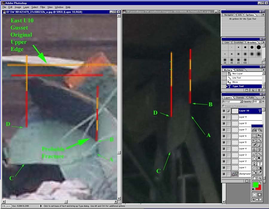
By taking two distances visible in both pre- and post collapse imagery, distances AB and CD in both panes, and comparing them to distances only visible in pre-collapse imagery, I was able to approximate the U10 East Truss gusset for size, orientation and scale, and flatten it back out, in the post collapse imagery, so we have a better idea exactly where the fracture took place, and can speculate as to cause:
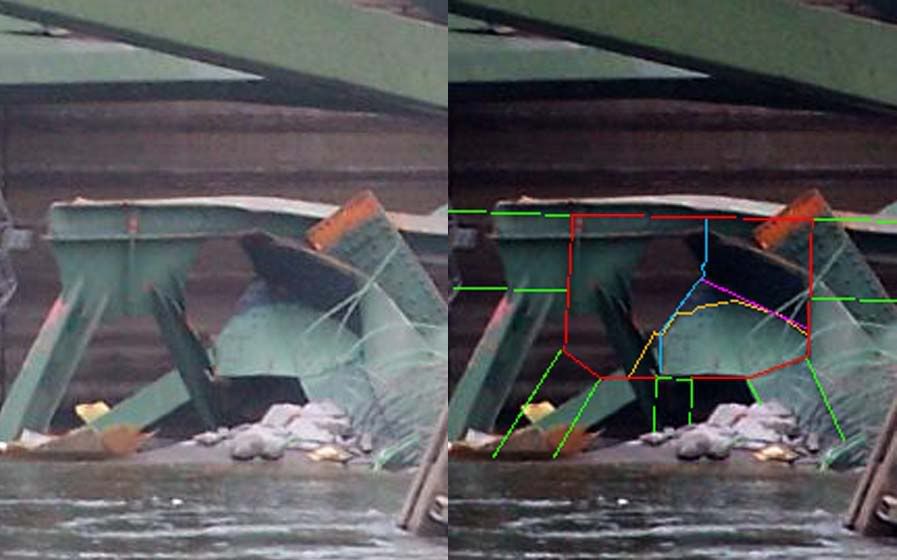
In the above image, right pane, the U10 gusset is outlined in red, the original structural members connected by U10 are marked in green, the pre-collapse discoloration of the U10 gusset is marked in yellow, the post collapse fracture line is marked in blue, and the post collapse fracture/folding of U10 is marked in violet.
The image below shows a wider view, including the reconstructed U10 gusset, with several interesting points labelled:
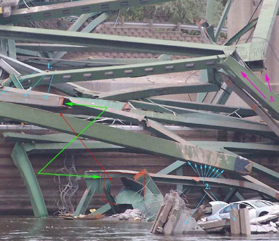
At left center, the U9-U10 topchord shows a longitudinal scar, marked with the arrows emanating from the numeral 1. In my opinion, this probably indicates that the U9-U10 topchord slid out from under a considerable gravity load during early failure. In other words, the road deck did not fail precisely at the U10 gusset, it broke further south, and a big piece of road deck scarred the U9-U10 top chord on the way down.
The green arrow shows how the two pieces fit together before the collapse, and the red arrow shows a piece of the U10 gusset still attached to the U9-U10 topchord. Under extreme magnification, the U10 gusset fragment still attached to the U9-U10 topchord shows the same discoloration noted previously.
Additionally, the above image reveals another interesting observation. Scrapes and discoloration on the collapsed L9-U10 diagonal clearly match the deck concrete, as indicated by the arrows emanating from the numeral 2. The L9-U10 diagonal came to rest upside down after the collpase, and the radial nature of these scrapes is clearly apparant.
Either an explosive fracture of the bridge deck took place in close proximity to this member, or else this member was subject to a prolonged shower of fractured concrete debris as it fell, and the scuff marks, and therefore the fall line of the concrete, changed dynamically with respect to time. Put simply, the L9-U10 diagonal was scuffed by falling concrete and the steel beam was rotating about its L9 gusset as it collapsed.
Since the scar on the topchord is, in my opinion, too pronounced to have been caused by a small chunk of falling road deck, then they were more likely to have been caused by a significant piece of road deck, probably still attached to the U10-U11 section of top chord. That tends to rule out an explosive concrete fracture in close proximity to the L9-U10 diagonal, making the L9-U10 rotation about the L9 gusset as it fell the more likely explanation.
This is important, in my opinion, because it essentially negates any other logical trigger point for the main span collapse. If the U10 gusset had fractured late in the collapse sequence, we would not see this kind of scarring. If this section of the main span fell as a unit, the scuffing on the L9-U10 diagonal would be in parallel lines, not the radial pattern we actually see.
There is further evidence for this. An end on telephoto view of the West Truss L7-L8 bottom chord shows a...considerable...longitudinal deflection. This massive member is curved about one foot. After the East Truss failed and began to collapse, the West Truss was left supporting the entire main span. This overloaded the West Truss to the point where the bottom chord curved downward, and to the point where the West Truss L9 gusset didn't simply fracture, it shattered like a piece of glass, as indicated by the arrows emanating from the numeral 3 in the image above.
As I said before, I am 100% satisfied as to the collapse sequence of the main span, and that the U10 East Truss gusset was the trigger for mainspan collapse. Note, I do NOT say that the East Truss U10 gusset fracture failed the I-35 bridge, I say it failed the I-35 mainspan. It is still mathematically possible a short section of deck well south of the river fell first, and the jarring vibrations from that pushed U10 over the edge, but I have no reasonable doubt any longer that the East Truss U10 gusset triggered mainspan failure.
It is therefore highly interesting to note that a University of Minnesota study explicitly focused on the U10 and corresponding gussets in 2001. The full report of this study can be read here:
http://www.dot.state.mn.us/i35wbridge/pdfs/umn-study-fatigue-evaluation-br9340.pdf
The study concluded that no normal traffic load would exceed bridge design standards, not by theoretical mathematics, but by actually measuring the strain, under real traffic loads, at the precise gusset which triggered mainspan collapse.
Going back to the above image, it is clear to me that the discoloration of the U10 East Truss gusset indicated it was not painted, or the paint flaked off, after the bridge was assembled. The U10 gusset discoloration exactly matches, per Photoshop color balance analysis, the preassembly paint now exposed on the L9-U10 bottom chord, where the U10 gusset was torn away. You can't pint under a gusset after the bridge is assembled, and for reasons unknown, part of the U10 gusset's coloration matches unpainted steel under the gusset.
In summary, the U10 gusset fractured under load, and triggered mainspan collapse. The U10 gusset had strain gauges attached to it in a 2001 scientific test, and was pronounced to exceed the requirements to support any reasonable traffic load that was placed on it. The U10 gusset was, for reasons never explained or even discussed, never painted since the bridge was assembled, or subjected to such extreme conditions that all successive layers of paint flaked off. The fracture lines of the U10 gusset nearly or precisely match the discoloration.
Unfortunately, science is a lot easier to predict and analyze than politics. I can't say why the East Truss U10 gusset was never painted or lost most of its paint. I can't approximate why this was not discussed in any of the bridge inspection reports for the last 10 years. All I can say is that U10 is where the mainspan failed, U10 looked different than any other gusset visible in pre-collapse imagery, and the U10 had been studied, closely, and recently.
If I had to speculate...well, this image, of a similar gusset elsewhere on the bridge, is probably where my speculation would begin:
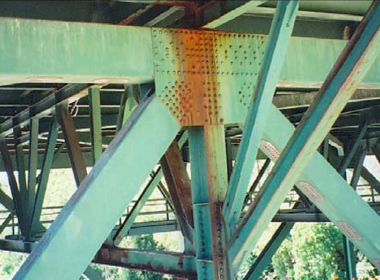
Not hard to imagine an L shaped fracture along those rust lines, and rivet lines, is it?
Which brings us to this question...
Why are the inspection reports word for word identical, even though they were conducted two years apart, over decades?
If the reports were cut and pasted, were the inspections themselves actually conducted? If the inspections were conducted, why didn't any inspectors ever comment on the obvious and unique coloration of the gusset which failed the bridge? The discoloration that precisely foretold the fracture line?
If any of our Minnesota Free Republic brothers and sisters can point a good Conservative newspaper to this post, perhaps they can ask these same questions publicly, and get answers, before any other skeletons come out of the closet by surprise, and kill some more bridge crossers.